***Click here for the Index of the TKB Build ***
I've cut the ribbon strip to about 60com..... could prob make it a bit longer to make attachment to the mother board easier in the future.
(sorry for the out of focus pic).
To quote the 1970 instructions:
"Cut the ribbon cable so that each wire is exactly 1" shorter than the adjacent wire, as shown in the diagram above. This can be done by peeling the blue wire back to 6" from the plug, then peeling the green wire to 7" from the plug, then the yellow wire to 8" and so on. The longest wire will be the brown wire. The length of the brown wire should be about 22". Usually the ribbon cables packed with the TKB kits ore much longer. Strip away about l/8 of insulation and tin the leads for ease of soldering in the following steps."

 ....
....
It attaches to the mother board thus:

Below is a pic of the header 70's style:

To quote the 1970's building the TKB kit instruction manual:
"The wiring of the TKB is made easier with the use of 16-pin 'header'
plugs that fit into IC sockets on the KBD PC board. The main wiring
consists of connecting the various ground busses and signal busses to
form a matrix with the 64 potentiometers".


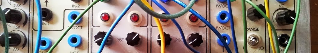
Next I installed the wires connecting the touch board with the 16 red pulse out sockets
In the clone they run under the pot boards.


Finally soldering these wires to the touch board.
First, the connections to the pulse outs.

The 1970 instructions read as follows:
"Position the TOUCH assembly on the panel face where it will later be installed, but do not peel away the backing from the double stick tape. Using masking tape, tape the TOUCH assembly so that it is in an open position as shown in the diagram. Now the wires from the red Pulse Output Jacks can be installed, feeding under the potentiometer wiring matrix, through the cut-outs on the panel, to the LED pads on the underside of the TOUCH Panel. These sixteen pads are in the center of the underneath of the TOUCH Panel. The end pads are split into two sections. The wire to pad 17 will be soldered onto one section as seen from the diagram."


Next : Installing the S2 & S3 Ribbon Cables
-------------------------------------------------------------------------------------------------------------
No comments:
Post a Comment