so far in modular synthesizers. It's not a chaos module but instead acts like a neuron which is the
core component of the brain, spinal cord & CNS.
The features that define a neuron are electrical excitability and the presence of synapses
that transmit signals to other cells. Of course the brain is made up of trillions of tiny neurons
and this module represents just one.
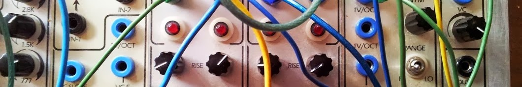
The NLC Neuron can be fed up to 3 inputs (eg LFO, sequencer or EG signals). It's output
can be fed to a filter or VCO (to control pitch on the oscillator, or cutoff on a VCF) or
to more neurons for some really crazy fun.

Andrew has put up a few useful links:
1. The Neuron Panel (4U Serge format)
2. Difference Rectifier / Neuron build doc.10 Jan 2013
3. Two Neurons build doc. 8 Jan 2012
4. Difference Rectifier Data, schematics, video, etc
5. WAMOD build notes
Muffs has a great thread too:
https://www.muffwiggler.com/forum/viewtopic.php?t=45741&postdays=0&postorder=asc&start=0
Here are some pics of the virgin PCBs & face plate.


The PCB on the right requites extra wiring to the jacks so is probably better suited for other formats like 4U.
It uses one TL 074 IC


I'll just be doing the Eurorack module for now, so the following pics are for Euro only.
Headers first:


Time for the 100k Linear pots (100B)

We now need ten 3.5mm jacks:


After the jacks are soldered connect the grounds with scrap wire offcuts.

You're Done.

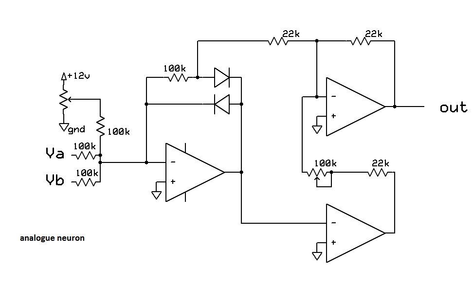
The Difference Rectifier:
There is a +ve & -ve output.
The output is the difference between the voltages of the two input signals, this difference is then split into iits positive and negative components. "what does it all mean? A one op amp, 8 resistor and 2 diodes circuit that churns out weirdness". The schematic and formula are here - http://www.sdiy.org/pinky/data/dif.html
---------------------------------------------------------------------------------------------------
Click here to return to the NLC (NonLinearCircuit) Build Index:
http://djjondent.blogspot.com.au/2015/03/non-linear-circuits-ncl-index.html
What are EG Signals?
ReplyDeleteEnvelope Generator
Delete