Thursday 31 October 2019

Yamaha DX7 - FM & Timbre in a digital world

 I have recently been exploring the Yamaha DX7 and thinking about how it compares with standard analog subtractive synthesizers....... and contrasting Analog FM with Digital FM

There is something very special about the DX7 and how it produces sounds.
The Yamaha DX7 is of course digital and for many, the DX7 = FM synthesis.

However, FM isn't the sole domain of digital. FM existed in the analog world before the DX range was produced. Below is a pic of a Buchla oscillator... the 158. You can see that Don was very much into wave shaping & FM. This module dates from around 1968/69.


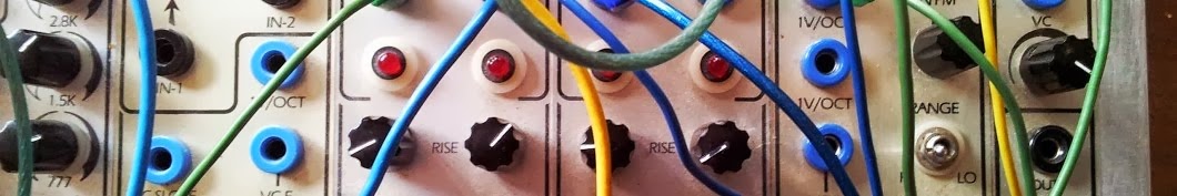
The pic below is of a Buchla 208 with its analog FM, dating from 1973.

Notice the word "timbre".

So in a non FM analog subtractive synth you usually start with harmonically rich wave forms like saw, square, etc. and you use filters to smooth the sound out a bit (technically we are subtracting overtones).
In analog FM synthesis, you start with a wave form and you then use other waves to distort it.... to create new tones & harmonics.


The best way to see this is with a spectrum analyser. This will show the additional harmonics created by the FM process.

Timbre

We come across this term again and again. It is also called tone or colour. What exactly is it?
It's one of the 3 main parameters of sound. ...which are volume, pitch & timbre.

The Oxford dictionary says that
"timbre" describes those characteristics which allow the ear to distinguish sounds which have the same pitch and loudness.

For example a piano, a flute and a guitar may all play the same (frequency) note, at the same (amplitude) loudness, but we can still tell them apart. This is due to their different timbres.

The timbre of a sound depends on its wave form. Though the frequency & amplitude may stay the same what varies are the number of overtones, or harmonics, that are present, their frequencies, and their relative intensities. 

To elaborate further, the timbre of a tuning fork is clear and pure because the sound it produces is almost without overtones. It vibrates at 440Hz. This is known as it's fundamental frequency.
You can use this fork to tune our piano, flute or guitar to 440 Hz (Middle A), but each instrument will sound different because they have unique overtones which are related to the fundamental.

Harmonic          Frequency
First                   440 Hz
Second               880 Hz
Third                  1320Hz
Fourth                1760Hz
Fifth                   2200Hz

To calculate the next harmonic, you of course just add 440.
  These relationships appear to be very important when using the Yamaha DX FM system.
This is where concept of Frequency Modulation Ratios is impt. 
Harmonic overtones are created based on the ratio between the carrier frequency & the modulator frequency. Musically pleasing overtones are based on simple fractional ratios like 1:2, 1:3, 1:5, etc
Complex fractional ratios like 1.73 produce complex waveforms when combined with operators set to other ratios.
 
Below is a list of the ratios used in the DX21
 

What's important to remember is that when you hear any sound (in nature or music) you are hearing lots of different frequencies all mixed together.... fundamentals, harmonics of the fundamentals, 
dis-harmonics / en-harmonics of the fundamental, etc etc..... this is timbre.

More harmonics = more "musical" sounds
More dis-harmonics = more "non-musical" sounds

Digital synths generally produce sounds in two ways ... FM or additive
Additive digital synths like the Fairlight and the Synclavier can specify a fundamental frequency and add overtones (of harmonics & disharmonics) to create new sounds.  The Fairlight allows sampling where it will analyse a inputted sound, and recreate the sound using its additive synthesis ability.

Though the DX7 can do some additive, this is not it's main way of making new sounds.
It's method uses Digital FM
It's all accomplished in a virtual world consisting (not of waveforms distorting one another),. but of programs in a computer calculating what would have happened if these waveforms had really existed and were distorting one another.

The core of the DX7 is the operator.
Its not a physicial thing like a string on a guitar or an oscillating electrical signal.
It's a bit of software.
You can picture it something like this:
The Oscillator is the sound source.
It generates numbers.

The operator also has a digital amplifier and EG
The amplifier's job is to increase or decrease those numbers exiting the oscillator.
It may be changing volume (if the operator is a carrier).
The EG will send numbers (issuing software instructions) to effect the amplifier.... its changing volume over time in this example.

Note That the operators oscillator has two inputs:
1. pitch data
2. modulation data

When the output of one operator is patched into the input of another operator, the result is a complex waveform. This is the essence of FM synthesis.
By varying the ratio of the modulator & carrier frequencies, and by varying the envelope of the modulator, you can create some very complex waveforms.

They use DACs to convert those numbers to analog voltages which we can hear.

----------------------------
FM Index
--------------------------- 

Saturday 26 October 2019

DX7 - Basic - Play & Function Modes - getting started

 There are 3 main modes of operation on the DX7

1. Edit (purple-blue)
2. Play (white)
3. Function (brown)


Everything is colour coded

Play Mode


Play Mode (white) is the simpliest and a good place to start.
Here you can access the sounds contained in the internal & external memory.


The green buttons above PLAY let you select between internal and external sounds.
Just press either green button to activate the 32 (white) switches. Then press the switch to select the preset.


External sounds can be either ROM or RAM.


ROM or Read only memory cartridges are non erasable.
You cannot write data to a ROM cartridge.
Each ROM cartridge contains 64 sounds or presets organised into 2 sides... sides A & B. (32 on each side).
Selecting the side (A or B) is accomplished with the select switch on the cartridge itself.

RAM =Random Access Memory .... this is very flexible ... you can both read and write data to it.
This contains 32 voices


Function Mode

Press the brown function  key to enter this mode.
It covers various effects you can apply while playing (like aftertouch & Modulation wheel) as well as things like voice data load/save operations and checking the battery.

Functions parameters cannot be saved to memory after the DX is turned off.

1.     Master Tune
2.      Poly/Mono
3/4.   Pitch Bend (range & Step)
5/6/7 Portamento (mode, Glissando, time)
9.        Edit recall
10.     Voice Initialize
11.      Cartridge formatting
14        Battery Check
15/16  Cartridge (save & Load)
17/18/19/20 Modulation Wheel - range, pitch, amplitude, EG Bias
21/22/23/24 Foot Control - range, pitch, amplitude, EG Bias
25/26/27/28 Breath Control - range, pitch, amplitude, EG Bias
29/30/31/32 After touch - range, pitch, amplitude, EG Bias

 -----------------------


1.     Master Tune
Adjusts the overall tuning ... 150% range. Use the data entry slider to adjust.

2.    Poly/Mono
Controls mono vs poly voice
Use Data Entry -1 for poly , and +1 for mono

3/4.   Pitch Bend (range & Step)
 Range: between 0 to 12.
              0 = no pitch bend.  12 = 2 oct range
Step : Between 0 to 12
           0 = smooth pitchbend with no steps.
           1 =  semitone steps
          12 = 1 octave steps.

5/6/7 Portamento (mode, Glissando, time)
Portamento effect depends on mono vs poly mode
eg: on mono use Data Entry -1 for fingered porta , and +1 for  full time porta
(see manual)
Glissando - adjusts speed of portamento
----------------------------------------


9.  Edit recall
Allows you to recall a voice that was previously being edited or created.
 Use the DATA ENTRY "yes key"

10.     Voice Initialize
This sets up a basic voice for you to edit and create new voices.
Press the DATA ENTRY "yes key "

11.      Cartridge formatting.
Interestingly this is not written on the DX7 itself. 
This formats your RAM cartridge
 Press the DATA ENTRY "yes key "

 14        Battery Check
Battery voltage should be between 2.2 to 3V.

15/16  Cartridge (save & Load)
Save= this saves the 32 internal memeory voices to a cartridge.
Load= This loads all 32 voices from a cartridge into internal memory.

--------------------------------------------------------------


17/18/19/20    Modulation Wheel
Used to control the amount of LFO modulation to range, pitch, amplitude, EG Bias
Range : 0 to 99
Pitch : on or off
Amplitude : on or off

 ----------------------------------


 21/22/23/24 Foot Control - range, pitch, amplitude, EG Bias

 ---------------------------------------


25/26/27/28 Breath Control - range, pitch, amplitude, EG Bias
29/30/31/32 After touch - range, pitch, amplitude, EG Bias


----------------------------
FM Index
--------------------------- 

Thursday 24 October 2019

Pioneer SQuid - projects

 You can store up to 128 projects.
Each project contains 16 midi tracks
Each track can contain up to 64 patterns
 
To load a existing Project
1. Press Global button
2. Turn rotary knob till "Open (by name)".
3. Turn the encoder till the project to want is displayed.
4. Press the encoder to select
 
To create a new project 
1. Press Global button
2. Turn rotary knob till "Create New"
3. turn rotaty to seleck "OK", then press it.
4. A new project will have been created.
    It will be named something generic like "Project 1 or 2 etc"

To Name & Save a project.
1. Press Global button
2. Turn rotary knob till you find the project. 
3. Press the encoder
4. Turn the rotary encoder till "Save As".
5. Press the encoder
6. now you can rename the track.
6a. To Delete a character : Shift + Back
6b. use the arrow left/right to move the cursor
6c. To insert a space : Shift + press the encoder
 
To Delete  whole project
1. Press Global button
2. Turn rotary knob till you find "delete".
3. Press the encoder


DX 7 - Keyboard Level Scaling


Keyboard Scaling is a parameter found in many keyboards. It's a way manufacturers allow sounds to be altered smoothly across a keyboard (in an attempt to make acoustic type sounds more realistic across the entire range of the keyboard) . In many modern  keyboards level scaling changes the loudness of the sound. Many analog synths use this feature to control filter cutoff from the lower to higher octaves.
It's sometimes called keyboard tracking or keyboard following.

The DX7s Keyboard Level Scaling settings allow the envelope levels to be adjusted across the keyboard. 


The break points sets the point to split the keyboard's scaling.
ie.. what the DX7 treats as a "high note" and what it treats as a low note. 
The breakpoint can be specified anywhere between A1 & C8

 Level scaling on the DX7 allows you to change the level of a modulator or a carrier depending on where you play on the keyboard. For example, you can slowly decrease the level of modulation as you go up the keyboard.

Once you set where the break point is, you can then choose the type of curve (of the envelopes)to the left & right of the breakpoint. Pressing the CURVE key alternates between R KEY SCALING and L KEY SCALING displays. Four different curves are available as shown in the figure.
 For example, will the operator increase or decrease in volume as you go up the keyboard?
Will this change be in a linear or exponential manner?

The depth of each curve varies between a 0 to 99 range.
A zero setting results in a flat (no variation) curve.
A 99 setting produces a maximum scaling depth.

 Keyboard scaling is a separate menu on the standard DX7. Go to edit mode and click through all the menus until you find Keyb Scaling settings.
By giving each operator different values, you can get lots of interesting effects.
Scaling the modulators will make the sound brighter as you go up the keyboard. This emulates many real instruments.

----------------------------
FM Index
---------------------------

Wednesday 23 October 2019

Tathra

This was part of out road trip to the Bega Synth Festival.

Tathra is a very beautiful seaside village ON THE Sapphire Coast.


This is the old warf.


Tathra is about 18Km from Bega


For more travel postcards click here:

FM Index

General

+ FM synthesis Timeline
+ Timbre & Digital vs Analog FM
+ Yamaha FM synthesis Chips
+ Simple FM synth (Chris Muir)

DAFM synth

+ Build notes
+ My quick start notes on the DAFAM

KORG
 + Digitakt & Korg Volca FM - patch notes sending / receiving CC messages

Wirehead Freaq FM

Synth & Modular Music Jam - Wollongong - ProSound & Lighting

Prosound & Lighting are organising a synthesizer event in Wollongong on Sat the 7th December.


There will be live performances on all types of synthesizers (modular, non-modular, keyboards, drum machines, etc).

There will be jumping castles, etc for the kids.


 Prosound held a similar event in 2017 which was very successful.

This is a family event and will be held in the carpark of the Pro-sound showroom in Flinders Street Wollongong.

Starting time : 2.30 pm
Finishing time : 6.00pm

Contact:
Claude Spinelli
Prosound
16 Flinders St, Wollongong NSW 2500
Phone: (02) 4226 1177


Links:
+ New Sound Waves
+ Prosound & Lighting, Wollongong... Website
+ Prosound FaceBook
+ Face Book event page

FM synthesis - timeline

This is a brief list of FM synthesizers.

1967
Discovered by John Chowning in 1967

1973
+Yamaha first licensed John Chowning’s FM synthesis technology from Stanford University

"It should be remembered that  Don Buchla implemented FM on his instruments in the mid-1960s, prior to Yamaha's patent. His 158, 258 and 259 dual oscillator modules had a specific FM control voltage input, and the model 208 (Music Easel) had a modulation oscillator hard-wired to allow FM as well as AM of the primary oscillator. These early applications used analog oscillators" (Wikipedia).

1977
+ Synclavier I

1980
+ Synclavier II

1981
+ Yamaha GS-1
    8-operator FM synthesizer (4 Carrier/4 Modulator/8 EG)

1983
+Yamaha DX 7 Mk 1
  6 operators and 32 algorithms. 
+Yamaha DX 1 - only 140 produced. Flagship of the DX series.
   Dual 6 operators
+ Yamaha DX 9
  4 operators, 8 algorithms

1984
+ Synclavier III
+ Yamaha TX816 Tone Generator System
    Rack unit taking up to eight TF1 modules. Each module was a 6 operator/32 algorithm synth.
+ Yamaha TX 216 Tone Generator System
    Rack unit The TX216 contains two TFIs (2 DX7 sound engines), mounted in the same
    4U rack frame which is capable of powering up to 8 TF1 sound modules.
    Each TF1 module consists of a 16-voice, 6-operator FM synth
+ Yamaha CX5M - MSX computer
    8 voice. Yamaha produced a range of cartridges including a programmer
    for Yamaha's DX range of FM keyboards and a real-time sequencer.

1985
+Yamaha DX 5
   Dual 6 operator
+Yamaha DX 21
   4 operators and 8 algorithms.
+Yamaha DX 27
  4 operators. 8 voice polyphony and 192 preset and 24 user writable patches.
+Yamaha DX 27s
  4 operators
+Yamaha DX 100 (same as the DX27 but with mini keyboard)
   4 operators, 8 algorithms. (Chromeo, Aphex Twin & Autechre)
   8 voice polyphony and 192 preset and 24 user writable patches.
+ Yamaha TX 7 - desktop module version of DX7
    6 FM operators and 32 algorithms

1986
+ Yamaha DX7 MkIID / DX7 MkIIFD
   6 operators and 32 algorithms. (upgraded the DX7 Mk I from 12 to 16 bit, Stereo added.
   Also allowed "keyboard split" sounds & increased the number of voices to 64)
+ Yamaha FB-01 Synth module
   4 operator
+ Yamaha PSS-170 - two-operator preset FM synth. Synthesizer Chip: YM2413
+ Yamaha PSS-270 Synthesizer Chip: YM2413 (FM 2-operator)

1987 
+ Yamaha TX81z - rack module (half-space 1U rack model of the DX11)
   4 operator (Yamaha's first true multitimbral FM synth)
+ Yamaha TX802 - rack module (basically a rack-module version of the DX7mkII)
   6 operator, 32 algorithms 
+ Yamaha DX 7s 
    6 operator, 32 algorithms
+ Korg DS-8
    4 operators per voice. 8 voices of polyphony and 8 parts multitimbrality
    The DS-8 uses the same YM2151 / YM2164 OPM chip set as the Yamaha DS-9, 
    FB-01, and CX5M computer
+ Korg 707 
   The 707 uses the same YM2151 / YM2164 OPM chip set as the Yamaha DS-9, 
   FB-01, and CX5M computer
+ Yamaha SHS-10 (shoulder Keyboard - Sholky - Keytar). 2 operators, 6 voices


1988
+ Yamaha DX 11
    4 operators , 
    8-part multitimbrality, whereas older DX synths (apart from the TX81z) were monotimbral.
     Instead of just sine waves, the DX11 offers 8 different waveforms. 
+ Yamaha TQ5 - tone generator / workstation
    4 operators (with 8 waveforms) per voice. 8 voices. Built-in digital effects and an 8-track sequencer
     8-parts multitimbrality
+ Yamaha PSS-140 - 2 operator. 100 preset sounds.,,,
     5 percussion sounds {closed cymbal, open cymbal, conga, snare, base}
+ Yamaha WT11 (1988) - designed to be used with a wind controller.
    The WT11 is IMO a greatly underrated module. 
    It shares the same Yamaha 4-op engine as the DX11 and the TX81Z, adding the 
    PEG (pitch envelope) of the DX11.

 1989
+Yamaha V50 FM synth workstation
   4 operator . Has a drum machine, & a 16,000 note sequencer
+ Yamaha SY77
    6 operator AFM synth with 45 algorithms, 3 feedback loops and 16 waveforms


1990
+Yamaha TG33 (Tone Generator) - desktop module. Combines FM with 12 bit rom samples
   2 digital FM operators (256 FM vector voices)
   32-note polyphony
   16 part multi-timbral
+Yamaha SY22 - keyboard. - Vector synthesis - Samples & FM sounds are combined using the joystick
   2 digital FM operators & ROM samples
+ Yamaha TG 77 (Tone Generator rack) - same as the SY77
   6 operator AFM synth with 45 algorithms, 3 feedback loops and 16 waveforms


1991
+ Yamaha SY99
    6 operator AFM synth

1992
+Yamaha SY35
   2FM operators & 2 (AWM) Digital acoustic Sample playback oscillators
    

1995
+Expiration of the Stanford University FM patent. 
  Digital FM synthesis can now be implemented freely by other manufacturers 

1998
+ Yamaha FS1R (rack)
    8 operator, Combines formant synthesis with FM.

2001
 +Yamaha DX 200
   6 Operator FM, 32 algorithms

2002
+ Native Instruments FM7 - software
   8 Operators (The first six operators (A-F) are modeled after the DX-series.)
   Instead of just sine waves therere are 32 ranging from sine to complex formant waves.
   32 algorithms ???

2005
+ Alesis Fusion 
+ Abelton Operator - hybrid synth combining FM, additive & subtractive synthesis.
    5 operators (4 main operators & a 5th LFO), 11 algorithms, 7 envelopes, multiple filters.
    It's possible to edit preset waves forms or draw your own by adjusting the oscillator’s 
    harmonic frequency.

2011
+ Korg Kronos
   6 operator
+ Teenage Engineering OP-1
    4 Operator (there are actually 10 interchangeable synthesis types of which FM is just one.)

2013
+ PX-7 Reason  (software) Rack
    6 operator,  32 selectable algorithms

2015
+ Yamaha ReFace DX
    4 operators 12 algorithms, 8 voices.
+ Dexed - free! Software. Can use it to control and program a real DX7. Its also a great way to
    load and save patches

2016
+ Yamaha Montage
    Hybrid synth (FM-X engine with AWM2, a sample-based synth engine.)
    FM-X is capable of  8 operators with 88 algorithms.
    Ability to process external audio and use it as a modulation source in its FM-X engine
+ Korg Volca FM
    6 operators, 32 algorithms, 3 voices
+ ALM Busy Circuits Akemie’s Taiko - eurorack
     4-operator FM, Six algorithms, 8 waveforms
+ ALM Busy Circuits Akemie’s Castle - eurorack
     4-operator FM, Six algorithms, 8 waveforms

2017
+ Synstrom Deluge
   2 carriers, 2 modulators,. 8 algorithms (4 operators ??)
+ Arturia DX7 V - software plugin
   6 operators (25 waveforms instead of just sine as with a DX7), 32 algorithms.

2018 
+Elektron Digitone
   4 operator 8 algorthims 
+ Yamaha MODX 
+ NERD Sequencer (XOR Electronics) 
     Four Operators

2019 
+ Arturia Microfreak
    2 operators  
+ Humble Audio Quad Operator & Algo (Eurorack)
   4 operators 
+ Kodamo Essence FM
   6 operators, 300 voice polyphony

2020
+ MegaFM Synth - Twisted Electrons
   4 operators, 8 algorithms. Uses a YM2612 chip.
+ PreenFM3
    6 operators, 16 voices


This list is by no means complete.
I'll add to it over time

Yamaha DX 7 - envelopes

The envelope generator will determine how the volume (amplitude) or timbre (tone) of a note will vary over time.

What is impt to know is whether the envelope is being applied to a carrier or a modulator operator.


Envelope modulation of a modulator will effect timbre.
Envelope modulation of a carrier will effect volume.
(this is kind of like envelopes applied to filters vs VCAs in subtractive synths)

The parameters that determine the shape of the envelope are RATE (R1 to R4) & LEVEL (L1 to L4).
The Rate parameters determine how long it takes the envelope to reach each level.
Each RATE and LEVEL can be set from 0 to 99
Each operator can have a unique envelope.

to be continued...............

----------------------------
FM Index
---------------------------

Tuesday 22 October 2019

Bodalla - Old Cheese Factory

This was part of our Road trip to the Bega Synth festival of 2019.


Sadly the old cheese factory was closed when we arrived.


God's country. Such a beautiful afternoon

For more travel postcards click here:

Buchla Power Supply Conventions

Buchla Power Supply conventions 

These PSUs changed over the decades so are confusing at times.
As I work my way through the modules that I own I'll update this post.
Please let me know if there are any errors.

Buchla 100
+15V, +24V, single ground.

Buchla 200 (early - Black Knob modules)
+15V, -15V, +/-24V, +5V, -5V, dual ground

Buchla 200 (late - "blue knob" modules)
+/-15 volts, +5 volts, +12 volts and 2 ground lines

Buchla 200e
Power on a Buchla 200e module is delivered from a  edac 306-010-500-102 connector.
The 200e cases come with a12 volt DC wallwart that connects to 3 DC-DC converters.
This is much safer & probably also helps in reducing background noise.

I've made some backup Buchla power supplies and the DC-DC converters  that I have successfully
used are:Cincon CHB75-12S05 (for the 5V),and two CHB75-12S15 for the +15/-15 lines.
CHB75-12S12 for the +12V.
If +24 is requited use a CHB75-12S24 DC/DC regulator. These codes are Mouser numbers.
1 Black - quiet ground
2 White: -15
3 Red: +15
4 Dark Green: +12
5 Orange: +5
6 Brown: noisy ground
7 polarizing key - no connection (use this to correctly orientate the EDAC.)
8 Yellow: i2c clock
9 Green: i2c data
10 no connection - (I often use this for supplying +24v)

==================================================================

 This is the type of connector you will see on a 200 and 200e system

1 Black - quiet ground
2 White: -15
3 Red: +15
4 NC
5 NC
6 Brown: noisy ground
7 NC
8 NC
9 NC
10  +24v

There are quite a few PSU's out in the market at the moment.
Of course the official Buchla supply is the standard and if you use anything else you do so at your own risk.

-----------------


Monday 21 October 2019

Yamaha DX7 - Operators & Algorithms

Some notes on using the DX 7.
Yamaha released the DX7 Mk1 in 1983.
I only just bought a Mark 1 about a week ago so there is a steep learning curve ahead.

These will be added to over time and hopefully help me to master FM synthesis.


FM synthesis was first developed by John Chowning in 1967 at Stanford Uni, then licensed to yamaha in 1973.it's very different to Subtractive synthesis. There are no VCOs, VCFs or VCAs..

It's kind of the opposite of a subtractive synth.
In a subtractive synth you start with harmonically rich wave forms like Saw, Square, etc. and you use filters to subtract those harsh frequencies... to smooth the sound out a bit.
In FM synthesis, you start with a sine wave and you then use other sine waves to distort it to create new
tones

Instead of the VCO, FM uses an operator.
This generates a sine wave.

The DX 7 has 6 sine wave operators
Operators are actually more than just oscillators.
They can be viewed as a package containing an oscillator, an amplifier & an envelope Generator.
The operators can be either a carrier or modulator.

Carrier - this controls the sound output.
Modulator - controls the harmonic content of a sound. It determines the shape of the waveform produced and therefore its timbre

By rearranging the operators, we can generate harmonically rich tones.
These arrangements are known as ALGORITHMs (there are 32 of these).

The operators on the bottom row of each algorithm are sound producing carriers. The ones above are modulators.


Algorithims determine how the 6 operators interact with each other.
There are 32 algorthims.
Picking the correct algorithm is the key to creating a patch.
Each algorithm is suited to a particular type of sound.

For example to make a:
Pad or texture sound.. ---- something complex with layers, ....we need something with multiple sounding operators or carriers.
To make a Bass or lead sound -- we might use an algorithm with less sound producing operators and more modulators.

The algorthims are divided into subgroubs that have similar structures.
(Stacking, Branching, Rooting and Carrier-only)
These groups, will help you to understand how they interact and their sounds

Group 1  - algorthms 1, 2,3, 4, 5, 6.

These are stacked algorithms.
2 to 4 operators.
2 towers to 3 towers.
Between these towers there is no frequency modulation. Instead they are added ... ie they are an example of Additive Synthesis.
These types pf algorthims are used for such things as
Strings ( A4 STRINGS ALG 2),
Piano ( A11E.PIANO 1 ALG 5).
Tubular Bells ( A26 TUB BELLS ALG 5).

Algorithm 2 consists of 2 independent towers with operators stacked on top of one another.
 gREAT for sounds with high harmonics like strings .
Notice also the feedback loop. You can control the amt of feedback by its Level & Output Level.
We use feedback operators to generate higher harmonically rich tones such as sawtooth waves.

We can also adjust the Frequency Ratio of each operator to generate particular harmonics.
The frequency relationships between modulators and carriers are very important.


+ A ratio of 1:1 (ie. equal frequencies) tend to produce a waveform roughly equivalent to a sawtooth.
If Operator 2 = 1.00
     Operator 1 = 1.00
we will generate a sawtooth sound

+ A ratio of 2:1 (modulator 2x the fundamental frequency) would produce
something more square-like. As you increase the ratio you will get more high-end fizz.
So if we change the ratio like so:
Operator 2 = 2.00
Operator 1 = 1.00
we will generate a square wave

If we change the ratio like so:( where the modulator was a non-integer multiple of the carrier)
Operator 2 =3.50
Operator 1 = 1.00
we will generate a metallic or a Bell Tone (in-harmonic tone)

 -------------------------------------------
Algorithm 5 is a bit more complex.
We have 3 independent towers with two operator stacking. This is great for bell & electric piano sounds.
In a DX7 with 6 operators, all can be detuned. So you can get amazing chorus like effects.
Like the "Epic pad" sound.
--------------------------------------------------------------------------------------------------------

Group 2 - Algorthms 7 to 18.

These are a mix of Tower & Branch (like a tree).

Of special note, Algorithms 16, 17 & 18 are pure frequency modulation. (there is no additive component). All FMs converge into operator 1.

 Use group 2 algorithms for things like Strings, Brass, Guitar, & Bass patches.
Examples: DX7 Voice ROM 1
A6 Strings (ALG 15)
A4 BRASS 3 (ALG 18)
A12 Guitar ( ALG 8)
A15 Bass 1 (ALG 16).

---------------------------------------------------------------------

Group 3 - Algorithms 19 to 25

These are rooting algos with or without a tower

There are at least 3 carriers in each of these algorithms.

Of particular note, Algos 23, 24 & 25 have one to 3 operators without any modulators.
These are pure sine wave carrier operators.
Group 3 algorithms are used for things like brass, Vibe & pipes.
For example see Voice ROM 1
A1 BRASS 1 (ALG 22),
A21 VIBE 1 (ALG 23)
A18 Pipes (ALG 19)

-----------------------------------------------------------------------------------------------

Group 4 - Algorithms 26 to 32

These are tower/ branch combinations..
They all have at least 1 pure sine wave carrier only operator.

These are good for organ & bell sounds
Eg : from Voice ROM 1
A17 E.ORGAN 1 (ALG 32)

The Algorithm 32 is the simpliest algorithm.
Each operator is independent. Each generates a sine wave.
There is no Frequency modulation. Thus this is an example of pure additive synthesis.

----------------------------
FM Index
---------------------------