noise,
Noise,
and MORE NOISE.
Filtering noise is really important when building your synth.
Lots of ways to do this and the method may vary depending on the scale ... does the noise effect the whole synth (the PSU) or a small part of a circuit.
Decoupling capacitors, Ferrite beads, Inductors, LC Filters ??
I guess before you do this, you need to ask the questions;
- Are you better off filtering the noise, or preventing noise in the first place?
- Is there actually much noise to begin with?
- Is any LC filter you might install making more noise than it is removing?
On the macro level, a common method is to use something like a LC filter. This often is found in the psu (the main power supply). An LC filter consists of inductors ( represented by the letter L)
connected in series with the power flow and capacitors (represented by the letter C) from the filtered voltage
to ground.
Ferrite Beads
A ferrite bead and capacitor is another form of LC Filter. It is often used to filter power for specific power pins on an IC. They are frequently used on sensitive parts of a circuit
like PLL’s & analog sections.
LC filters are used to keep noise in one section of the circuit from getting to another section.
Decouplig Caps.
A decoupling capacitor is a capacitor used to decouple one part of an electrical network (circuit) from another. Noise caused by other circuit elements is shunted through the capacitor, reducing the effect it has on the rest of the circuit. (Wikipedia)
Also known as bypass capacitors.
They act as energy reservoirs ... you will often see them close to ICs ... they help to smooth out any voltage fluctuations.
You can also use decoupling caps on your main power distrobution board.
Here is an example for eurorack:
NLC power distro board
Below is a LM7805 voltage regulator.
Notice the two decoupling capacitors:
The capacitors are placed between the power line & ground.
The 0.33uF
helps to smooth out any low-frequency changes in an input voltage.
The 0.1uF helps to smooth out any of the high-frequency noise at the output.
Combining these two caps helps to deliver a smooth uninterrupted voltage to your circuits.
As mentioned earlier, decoupling are often used with ICs. Logic circuits tend to do lots of sudden switching ... between on & off with not much in between..So decoupling caps help to smooth and stabilize the input voltage..... absorbing excess voltage if the voltage spikes suddenly, and providing more power to the IC should the voltage suddenly drop.
The decoupling capacitors are connected between your power source, whether that’s 5V or 3.3V, and ground. (Generally it's recommend to use a 100nF
ceramic capacitor and a larger 0.1-10uF electrolytic capacitor for each
integrated circuit).
Inductors
These are also called coils or chokes.
They are passive two terminal components.
Like capacitors, they store energy.
However, in this case, energy is stored as a magnetic field.
They are usually made up of a insulated wire, wound round a core (magnetic ... iron or ferrite).
We measure inductance in units of Henry (H).
1Henry = 1 volt of EMF across the inductor with 1 Amp of current.
The larger the number, the higher the inductance.
The higher the inductance, the more energy we can store and provide.
It will also take longer for the magnetic field to build.
This is a inductor from a Metromodular Eurorack PSU
The inductor will remove any voltage ripple .
Notice also the diode> this eliminates voltage spikes if the power is suddenly switched off.
Here is another inductor - Its SMD
Ferrite Beads.
Also called Ferrite chokes, cores, rings, blocks, EMI filters.
These are passive components that suppress high frequency noise.
They are often wrapped around cables to prevent the cable from acting like an antenna and receiving interference from other devices.
These are snap on ferrite beads. The upper pic shows one used at the end of a USB cable.
Ferrite beads convert Radio Frequency (RF) energy to heat. They are like a filter.
(Contrast this with inductors, which by design do not convert RF energy to heat, but rather offer a high impedance to RF.)
On the left is an inductor. To the right is a PCB ferrite bead.
You will probably have seen many of the PCB ferrite beads in DIY synth modules.
------------------------
Splitting ground planes.
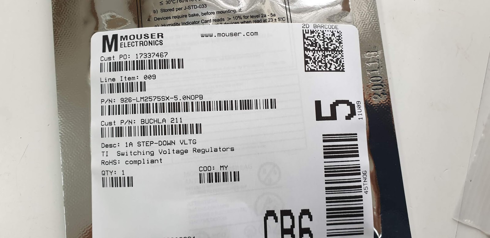
I recently read a great article from Texas Instruments re splitting ground planes as a way to reduce digital noise.
http://www.ti.com/lit/an/slyt512/slyt512.pdf
A
ground plane is an electrically conductive surface, usually connected to electrical ground.
On a PCB this is a large area of conductive material which is connected to the power supply ground terminal and serves as a return path for current from different components on the board.
Hoikka1 [CC BY-SA 3.0 (https://creativecommons.org/licenses/by-sa/3.0)]
Placing the ground planes below the relevant components and signal traces is also helpful. ...
maybe on a seperate layer of a multi-layer PCB .
This should help reduce electromagnetic interference, cross talk & ground loops.
I often see single ground planes on pcbs (with just analog components).
But if there are both analog and digital circuits on a single PCB, best practice seems to be to:
"separate the ground plane on the back layer into a digital section and
an analog section, but leave the two planes connected near the return to
the power supply. This ensures that digital signals do not follow a
return path beneath sensitive analog components....
It is a bad idea to completely split a ground plane and try to bring the sections to the same potential using something like a ferrite bead, as this creates more EMI and noise problems ." (Altium resources)
I've always wondered why Don Buchla used two grounds on his power distro busses.
This may be the reason.
Two separate grounds for analog and digital.???
He never used this on the earlier 200 series.
This type of distro was first used in the 200e which of course uses digital components.
Other ways to reduce noise:
+ Use two separate supplies .. one for the analog & the other for digital
+ keep the analog & digital components separate & don't let their grounds touch.
But I think splitting your ground planes is a really neat idea.
Links
+ Altium
+ Texas Instruments


 -----------------------------------------------------------------------------------------------------