Showing posts with label AE Modular. Show all posts

Thursday, 9 April 2026

Tuesday, 7 November 2023

CD 4017 sequencer

Some notes to build a simple sequencer for the AE modular.
I started building a GATE sequencer then turned it into a melodic one.
This is my 3rd AE modular project ... the first was a LPG followed by a series of clock sources and LFOs

You can of course vary the circuit design to suit Euro, Serge, Buchla etc.
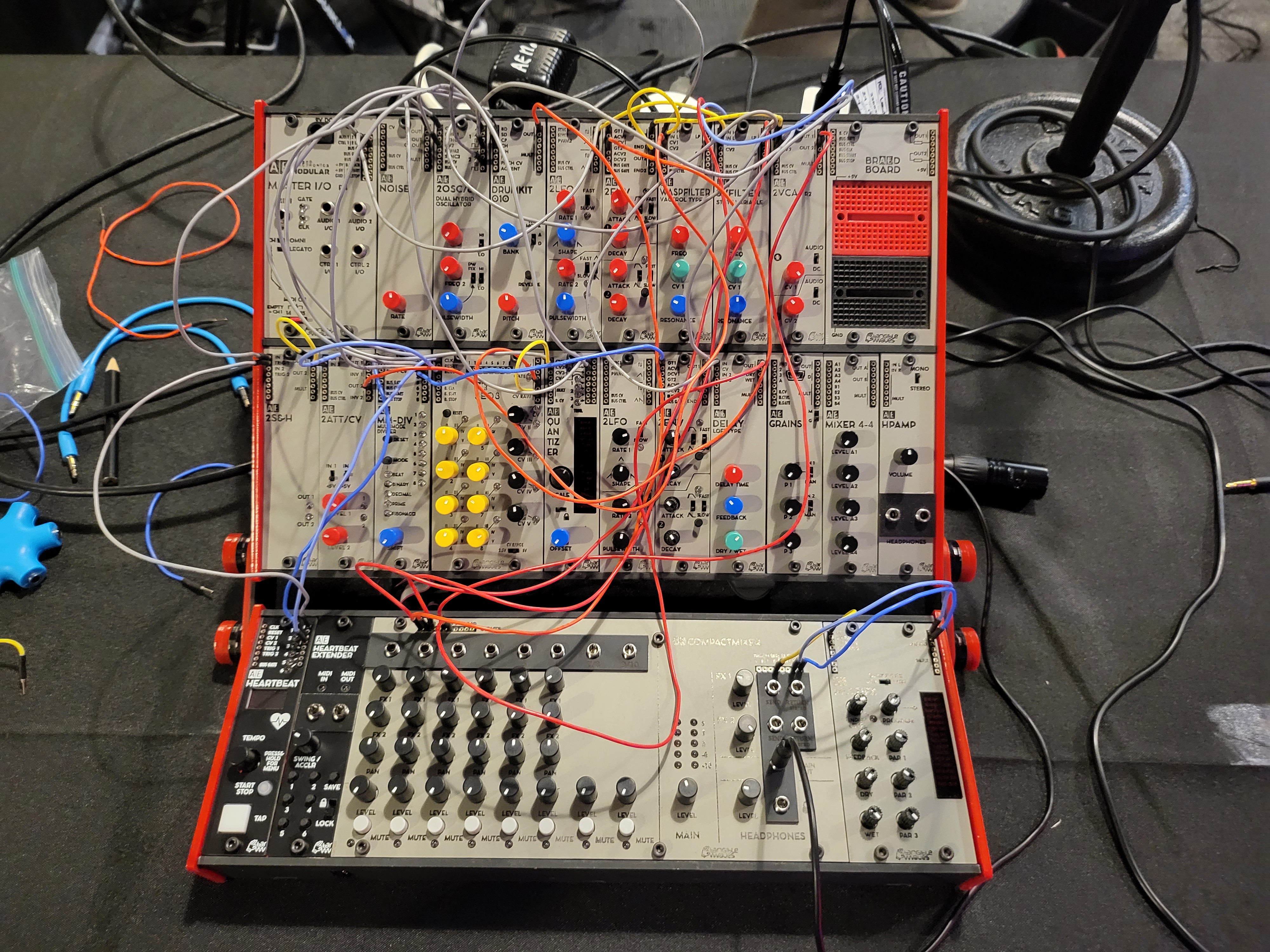
I think the AE modular is a great prototyping platform. It's the main reason I bought one.
The voltages are low & safe.... and breadboards use the same connection cables.
You can literally build your circuit on a breadboard and connect it directly to a modular and see how it works.

This project uses the CMOS CD4017 chip.
It's a 10 step counter.
The AE modular uses +5V so it's perfect


The 4017 has 10 outputs that go high everytime the clock input receives a gate/trigger.
Use something like a pulse from a LFO.

The outs are labelled 0 to 9
 
12 = carry out
        this “carries out” the clock input to an additional counter
13 = clock enable
        When it is “0” logic, the clock will get enabled, and the 
         counter advances one count for each clock pulse. But when “1” logic, 
         the clock input is stopped, and the counter will do nothing even 
         when a clock pulse arrives.
14 = clock in
15= clock reset
       Normally, it is “0” logic.
       When made “1” logic, the counter is reset to “0”.
16 = power (+3V to +15V
8 = gnd


---------------
Pins 13 and 15 must be connected.
They can't be left floating. 
Connect these to ground (with pull down 100k resistors).


Parts
+ CD4017
+ 100k resistor x 2 - for pins 13 & 15
+1N4148 diode to protect the clock input and allow only +ve voltages to pass into the chip.
+ use between 1K & 10K resistors to protect the LEDs from burning out.
+ 100k pots x 5 ... depends on the number of steps your sequencer will have. 
     I started with 4 steps. I'm building a 5 step now 
+ SP3T (single pole, three throw) .... adding a switch to change the step length.
+ TL072 or MCP602 (op amps)
+ 1N4148 diodes x 5 (pot outputs)

------------------------------------

I built the sequencer on the same board that I was using for the 6 LFOs


The LFO on the right is the clock source.
Its plugged into Pin 14 of the 4017.

Pins 13 and 15 must be connected.
They can't be left floating.  This is very impt !!!!
Connect these to ground (with pull down 100k resistors).


I had to choose how to drive the LEDs.
The 4017 can drive the LEDs on it's own ... does work, but it's a drain on the chip which
may lead to it burning out in the future.
A transistor is preferable since there is less load on the IC.
The trannie is a electronic switch
I used a 1k resistor and a NPN trannie ... 2n3094


Initially I just connected the outputs of the pots (pin 2) to a mult and then connected this to the VCOs CV input.
Seemed to work OK  but its actually a bit shoddy as current can flow back into the pot and interfere with the other outs. The fix is of course to add some diodes.

One final thing, .... buffer the output with an op-amp
Common op amps like the TL074, which I initially used  require a dual power supply which after I installed the 074, I remembered the AE modular doesn't have.


I'll experiment with LMV358 (dual), LMV324 (quad) and MCP6002,MPC602 & MCP6004 op amps.
These are called rail-to-rail opamps, meaning they work close to the supply voltages.

You may ask... What is the difference ?
The only difference is the allowable input and output voltage ranges. "Single-supply" opamps are opamps where the ranges are convenient for use in a single-supply configuration (such as with the AE modular). And yes, of course, you can use a dual supply with a single-supply op amp.

A TL072 may also be Ok for this project. 
I used one on my initial breadboard and it seemed to work


In the end I  used a MCP602
Supply:2.7V to 6V
I connected Vdd to +5V, and Vss to Gnd


The TL072 & MCP602 have the same pinout.

Here is the schemo 


-------------------------------

        Alternatives of 4017 are as follows:

IC-4060 — 14-Stage Ripple-Carry Counters/Dividers with Oscillators
IC-4020 — Binary Ripple Counter/Dividers, 14-Stage with oscillators
IC-4040 — 12-Stage Ripple-Carry Counters/Dividers
IC-4022 — Divide by 8 Counter IC


------------

to be continued....................

I may add a clock divider to this board, or a gate sequencer ??


Saturday, 7 October 2023

AE modular - techno system 4

I've been playing around with my small AE modular to build a compact live techno system.

I'll make a few recordings and upload one to the AE modular website as a contribution to their upcoming Aetherwaves album.
So if you have a AE modular system, why don't you record something and contribute to the community.
+ Submissions are due by midnight UTC, October 23rd
That's still 2 weeks to get your shit together.

The link is here:

The rules for the submission are:
+ Only new and previously unreleased material is allowed (please don't use that same track anywhere else after the release!)
+ All sounds must be from the AE Modular. 
+ Maximum length 5 Minutes
+ External effects may be used, such as reverb, delay, EQ, compressor, etc.


My system is missing some modules so I decided to build these.
There are 3 DIY modules:
A LFO, a low pass gate  & a sequencer.

This is the LPG:
Here is its link:

The master clock source is a simple oscillator.

This I DIY'ed (breadboarded) using a CD 40106 IC


The 4 step sequencer uses 2 breadboards.

Its using a CD 4017 chip.

I'll post links to the individual circuits soon.

Wednesday, 4 October 2023

CD 40106 IC - making simple oscillators & LFOs

Some notes on making simple LFOs and oscillators using a CD 40106 IC

I'm using a common CMOS  CD40106 chip.
The 40106 is a hex inverting Schmitt trigger.
It contains 6 inverters.


What makes this chip so special is that the inverters are relatively immune to circuit noise.
As with all CMOS chips, it's sensitive to static electricity.


Square wave oscillator

There is no CV, but this can be added later.
I added a LED to indicate when its active.


Parts
CD40106
LED (Blue)
3.3K LED resistor
10k
100k pot
0.1uF cap. (104) --- the value of this cap will determine the rate/speed of the oscillator

Square wave LFO
The circuit is very similar to the square wave oscillator 

It's important to ground any inputs you are not using. ... esp if you are not building all six oscillators.


Parts
CD40106
LED (Blue)
43K LED resistor
10k (experiment with this)
100k pot
1uf to 10uF cap. (Electro) - (cathode to gnd)


This cap will determine the rate/speed of the oscillator, so play around with its value.
The frequency is a function of the capacitor & resistor.
The higher the capacitor or resistor, the slower the frequency.

The cd 40106 can output two waves: square & triangle.
The square wave is pretty strong, but the triangle is quite weak, In order to use the triangle wave you will need to buffer it (with an op-amp).


re the potentiometer:
I only use 2 terminals.
Just use it as a variable resistor (not a voltage divider).


I'e also added a LDR to vary the resistance.
A ribbon strip would also work. 

-------------
As the CD 40106 chip has 6 inverting Schmitt triggers why not build 6 LFOs


..


.

All used a blue LED with a 2.7k resistor. I changed the cap values for each LFO to get different speeds

Out 1:  10K resistor + 100Kpot + 22uF cap

Out 2: 10K resistor + 100Kpot + 47uF cap

Out 3: 10K resistor + 100Kpot + 10uF cap

Out 4: 10K resistor + 100Kpot + 3.3 uF cap

Out 5: 10K resistor + 100Kpot + 1uF cap

Out 6: 10K resistor + 100Kpot + 100uF cap

Sunday, 1 October 2023

DIY Low Pass Gate using a AE Modular

 I've owned a small AE modular system for a few years and recently got hold of the DIY breadboard
 (BRAED BOARD) module


The AE modular system sounds fabulous. 
I purchased the system years ago to tinker with electronic circuits.
It uses +5v so you won't electrocute yourself.

The BRAED BOARD is a perfect addition for the experimenter in all of us.

Check out the AE modular wiki for more ideas

I am always running out of VCAs (they say you can never have enough).
So why not make a Buchla style LPG as my first project.
AE modular do also make a LPG module if DIY isn't your thing.
I think this module (called the LOPAG) is powered, and has the added option of switching to VCA mode.


This DIY version is passive & super super simple.

Parts
+ Vactrol 
+ LED
+ 10K resistor (x2)

Yes ! that's it.
Actually, you don't even need the LED. Its only a display.
You can of course get more complex, but those basic parts are all you need.

The basic schemo
The final choice of resistors will depend on the LED value, and the vactrol you use .
So experiment.

PS: if you can't find a vactrol, just roll your own.
You will need a LDR (light dependent resistor) , a LED & heat shrink.
More info about vactrols and how to roll your own here:


A short note: The LPG has low pass filtering characteristics as its name implies, 
so if you want a clean unadulterated sound, use a VCA. 


Some pics of my soldered version of this circuit using a NSL vactrol & a DIY vactrol.


Wednesday, 27 September 2023

Electric City @ Society City

Thanks to Ed (Elk Elektroniks) & Josh (Society City) for teaming up for the synth meet
last Sat (23rd Sept) in Wollongong, NSW (Australia).


Society City is a place for conscious creativity. 
It's primarily a book store that doubles a a co-op collective.

The volunteer-run art-space, cafe / bar, bookshop and community venue  that is perfect for arts, music and collaboration.
Electronic music, Jazz, Poetry, book reading, movie nights.
Everyone needs to utilise this space to keep it open and running for the local community.


Hopefully this will become a regular meeting.


Carsten's preparation (at my place) using the AE modular


Terry's video rig
..

Love seeing the module. esp with the Ukranian Trident. Slava Ukraini. Glory to the Heroes.


...


.


..


..


...


..


Sunday, 20 November 2022

The 5th Volt - Live at Elk Elektroniks in Wollongong

..

Thanks to Carsten (aka The 5th Volt) for the wonderful demo of the AE modular.

some pics.
This is the system before patching


The talk started with a blank canvas and finished with a composition.


The final patched system


For more information about the AE Modular system check out the official site:

You can also join The AE modular forum at:

All Carsten's videos, Instagram posts and Soundcloud clips are available at:

-------------------------------------
Elk elektroniks holds regular meetings... about every 6 to 8 weeks.

Elk Elektronik - Shop 3, 266-268 Crown St Wollongong

Instagram
 

Tuesday, 16 August 2022

ARP 2500 - sync with 0-c0ntrol & AE modular

 Some personal notes of syncing the ARP2500 with external gear.


I'm using the ARP2500 sequencer as the master clock.... the 1027 module

It's sending a clock into the 0-control clock input


The clock out from the 0-control goes into 
the AE modular


Its the orange cable ... into the 4 I/O.

The 4 I/O is a great & safe way to input/output external audio and Cv
Importantly, the sockets have overvoltage protection 
(as AE modular is limited to 5V).

They can be switched between audio and DC/CV signals.

The output from the 4 I/O is driving the trigger sequencer
TRIQ164


Finally, CV and gates/envelopes from the 0-control enter the AE modular via the Master I/O


I'm not sure if the input/output is voltage protected.
Though seems to work without any probs ....but if you're worried 
the external voltages might be too high, its better to use the 4 I/O
and keep things below the 5V level.