Initial efforts on getting some vector rescanning.
I'm using a LZX video synth and a Tektronix 620 monitor.
...
tHE patch is very simple.
Horizontal ramps into the X input.
Vertical ramps into the Y input
Video from the camera into the LZX "Color TBC" and out via the Color video encoder.
This video signal is then plugged into the Z input
The Passage, Bridge are boosting the signals
-------------------------
Patch 2
Slight variation on the first patch.
I'm now mixing the video signal into all 3 inputs.
Ramps and still going into the X & Y ins
....
---------------------------
Click here to access the Video Index page
Showing posts with label Vector Rescanning. Show all posts
Wednesday, 31 October 2018
Tektronix 620 monitor
Finally arrived.
And she survived the postal service.
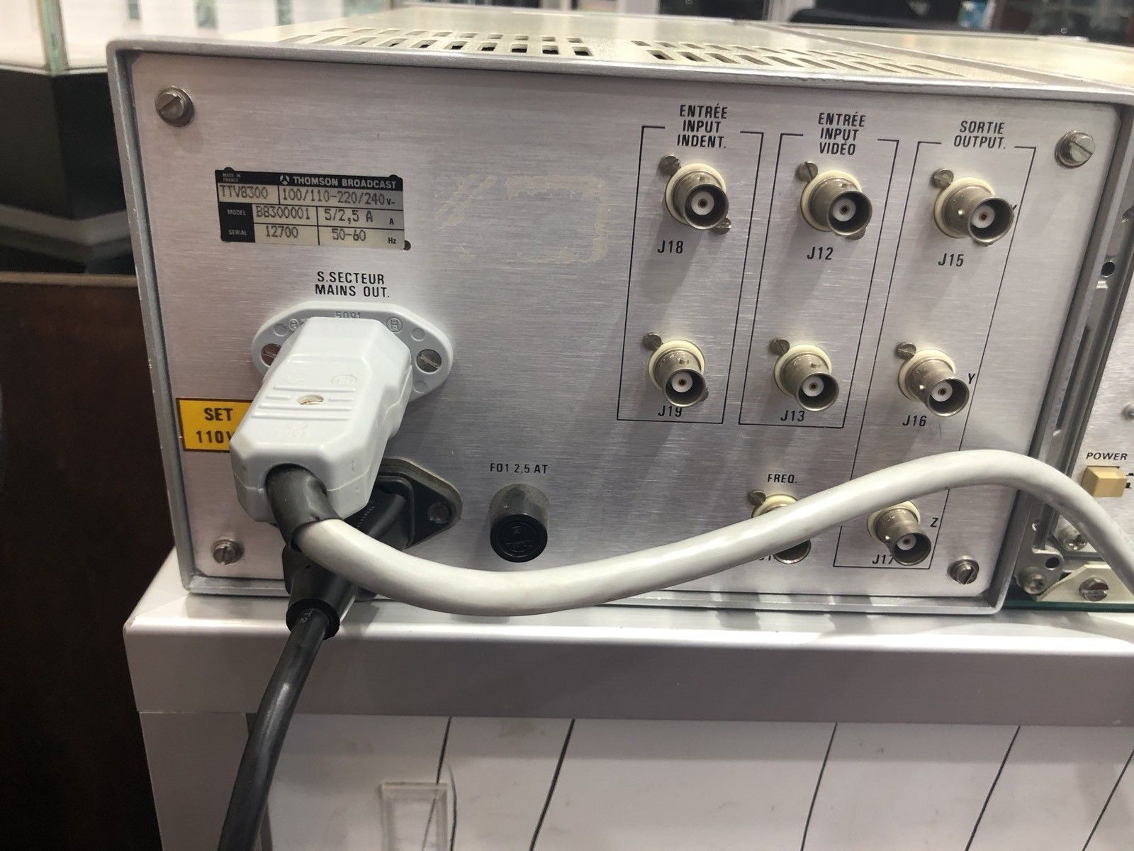
i'VE no idea what the Thomson module on the right does.
If anyone can help provide and info, manual, etc , I'd be very grateful.
This runs on 110V
I'm planning to use this to try vector rescanning.
It has the X, Y and Z inputs so hopefully it will work.
And she survived the postal service.
i'VE no idea what the Thomson module on the right does.
If anyone can help provide and info, manual, etc , I'd be very grateful.
This runs on 110V
I'm planning to use this to try vector rescanning.
It has the X, Y and Z inputs so hopefully it will work.
Saturday, 20 October 2018
Vectrex & LZX video synth - Curliing effects
I was trying to achieve vector rescanning on the vectrex but instead got some rather
interesting though unexpected "curling" effects.
Has anyone does something similar ?
some pics of the LZX setup.
tHE image on the vectrex was really small initially, but with amplification i was able to fill about 2/3 of the screen
---------------------------
Click here to access the Video Index page
interesting though unexpected "curling" effects.
Has anyone does something similar ?
some pics of the LZX setup.
tHE image on the vectrex was really small initially, but with amplification i was able to fill about 2/3 of the screen
I connected a
horizontal ramp to the X input, a vertical ramp to Y and the composite output
to the Z.
Maybe I should use a luma output ?
Click here to access the Video Index page
LZX - Cadet IV - Ramp generator
This is the fourth module in the series of LZX's Cadet DIY synthesizer.
Many thanks to Liz for making this possible.
A ramp generator is a signal generator which generates a ramp waveform.
It's actually a dual ramp generator which "creates 3 different fixed frequency ramp waveforms locked to the horizontal and vertical dimensions of a video display".
That 14 pin input header in the pic below is where the horizontal & vertical sync signals enter the module.
Modules with 14-Pin Sync Outputs include Visual Cortex, Video Sync Generator and Cadet I Sync Generator.
This will be essential if I want to do some vector rescanning.
The LM6172 op amp
This is used a lot in the cadet series. Get lots of these !!!
The TL431 - buy this in bulk too.
ICs (and other impt components) used in this build:
LM6172IN/NOPB (x2) ...this is a dual op amp... specified at ±5V power supply for low
voltage applications such as portable video systems.
TL431BQLPR (x3).... Adjustable Precision Shunt Regulator
TL431 shunt regulator circuit explained
TL072IP - standard op amp
SN74HC14N- - it's a hex schmitt trigger
TL074CN (x2) .....standard op amp
BS170 N-Channel...MOSFET...metal-oxide semiconductor field-effect transistor.
used for switching or amplifying signals.
The SN74HC14n .... its also used in the Cadet IX VCO though I don't think its responsible for the waveform generation in this circuit (please correct me if I'm wrong).
I think the ramp generators are built using mostly transistors.(2N3906/BS170)
For this to work, the voltage must be very precise... thus the use of the TL431.
This waveform increases steadly as the capacitor charges until it hits its peak and then decreases suddenly as the capacitor discharges.
iT'S DONE !!!
----------------------------------------------------------------------
Links:
LZX official
Muffs - Cadet series DIY/assembled
All about ramp generators
Youtube Ramp Generator Circuit built with Transistors
---------------------------
Click here to access the Video Index page
Many thanks to Liz for making this possible.
A ramp generator is a signal generator which generates a ramp waveform.
It's actually a dual ramp generator which "creates 3 different fixed frequency ramp waveforms locked to the horizontal and vertical dimensions of a video display".
That 14 pin input header in the pic below is where the horizontal & vertical sync signals enter the module.
Modules with 14-Pin Sync Outputs include Visual Cortex, Video Sync Generator and Cadet I Sync Generator.
This will be essential if I want to do some vector rescanning.
The LM6172 op amp
This is used a lot in the cadet series. Get lots of these !!!
The TL431 - buy this in bulk too.
ICs (and other impt components) used in this build:
LM6172IN/NOPB (x2) ...this is a dual op amp... specified at ±5V power supply for low
voltage applications such as portable video systems.
TL431BQLPR (x3).... Adjustable Precision Shunt Regulator
TL431 shunt regulator circuit explained
TL072IP - standard op amp
SN74HC14N- - it's a hex schmitt trigger
TL074CN (x2) .....standard op amp
BS170 N-Channel...MOSFET...metal-oxide semiconductor field-effect transistor.
used for switching or amplifying signals.
I think the ramp generators are built using mostly transistors.(2N3906/BS170)
For this to work, the voltage must be very precise... thus the use of the TL431.
This waveform increases steadly as the capacitor charges until it hits its peak and then decreases suddenly as the capacitor discharges.
Since this waveform repeats over and over again, this waveform generator appears as an oscillator.
iT'S DONE !!!
----------------------------------------------------------------------
Links:
LZX official
Muffs - Cadet series DIY/assembled
All about ramp generators
Youtube Ramp Generator Circuit built with Transistors
---------------------------
Click here to access the Video Index page
Friday, 19 October 2018
Rutt-Etra - Vector Rescanning - the perfect monitor?
A bit about vector rescanning
I've been trying to accomplish vector rescanning for years.Never really successfully.
Part of the problem I think has been my early confusion & lack of understanding of the different types of oscilloscopes, vectorscopes & waveform monitors (and I'm still learning).
Living in Australia, doesn't make it easier to find old working scopes from the 70's and 80's and attempts of posting them from the USA usually ends in tears. Postmen seem to love throwing delicate analog instruments around in their truck. I lost 3 scopes this way.
Two that have survived the rigours of FedEx & Australia post are the Tektronix T922 and 465B
Lovely scopes that I use all the time for standard audio waveform measurements .... but not 100% successful for Rutt-Etra stuff.
Tektronix T922
Tektronix T922 rear with z axis input.
Tektronix 465B
The two models that often come up in the various forums as working well for vector rescanning are the
Leader LBO 51MAC, and the Tektronix 620 .
(Unconfirmed ... Leader LBO-514A & Tektronix 608)
Leader LBO-51MAI just purchased this on ebay. It hasn't arrived yet, & I'm waiting with anticipation to see if it survives the trip.
And of course, there is the vectrex.
My understanding is that the vectrex isn't prefect for vector rescanning as it does not have the bandwidth ....but it kinda works in limited ways
It is better suited for lower frequency oscillographics.
However, if you still want to do vector rescanning you need:
1.Video Input to extract luma from your video source
2. H & V ramps generator .
Thus if you are using Cadet modules you only need one Ramps, a Sync Gen and an Input.
A LZX visual cortex (VC) has all of this.
Connect the horizontal ramp to the X, the vertical ramp to Y and the luma output (of the VC or the VideoInput) to the Z.
The Rutt/Etra Video Synthesizer is an analog raster manipulation device built in 1972 for image processing and real-time animation. The Rutt/Etra was co-invented by Steve Rutt and Bill Etra.
Links
+ Muffs- vector modification
+ Vectrex Hackaday
+ Hacking a vectrex - Lumpybanger
+ Zektor - using the vectrex monitor
+ Muffs - vector rescanning for dummies
+ Muffs - good oscilloscope for vector rescanning
+ Rutt-cadetra blog
+ Rutt/Etra Video Synthesizer Demo (1974) youtube
+ Rutt-Etra-izer
---------------------------
Click here to access the Video Index page
Tuesday, 16 October 2018
Vectrex - hack
Found a second Vectrex. :-)
I have two now, one to play and the second to use for vector rescanning.
This has come all the way from France.
As a retro gaming collector, it hurts to modify this. So I'll try to make as few changes as possible.
Time to open her up.
Be very very careful of the tube. Even after not being powered for weeks they can still retain lethal voltages. So discharge it first.
I used this screwdriver (place under the protective rubber CRT cap) which I attached to ground via the alligator clip. Listen for the pop !
I can't stress enough the risk of discharging the tube. If you are not sure what to do , get a qualified technician. These voltages can kill.
Some pics .. this is the CPU section
In the pic below, the CPU section is on the base, and the XYZ driver board is positioned vertically. It is to the left of the tube.
In the pics below, the XYZ board lies behind the heatsink.
You need to separate these two boards. and wire the XYZ inputs to the back.
I'll use 3.5mm jacks.
The inside of the jacks
Connect like this to return the Vectrex to normal so you can play games again
I could instead add a switch, though this would involve more holes & drilling.
I've attempted to keep any destruction of this vectrex to a minimum.
So the only permanent modification was drilling the 6 holes for the 3.5mm jacks. All the original wiring is preserved!!! So you can re-connect the wiring for gaming action!
Now that you've modded it what standard eurorack audio modules should you use??
In my test I used:
The elby matrix mixer is a real winner. The bluelantern Thruzero VCO & the steiner microVCO also worked nicely.
Other possible modules:
+ Synovatron CV tools, DPO, MATHS, Wogglebug.
"Maths is usually the Z input, I'm mainly just playing with the speed of the pulse - as if it's a really fast envelope.
Then two or more outs from both oscillators in the DPO are going to X & Y,..."
+ e340 for X & Y. -- cloud generator
+ Thonk/Fonitronik Cascade
+ If you have a ARP 2600 or a TTSH, the voltage processor is excellent for modifying the 3 input signals
+ Pip Slope and an O/A/x2 from ALM / Busy Circuits
+ PDO and Akemie's Castle
+ Clouds
+ 4MS Shifting Inverting Signal Mingler
It is better suited for lower frequency oscillographics.
However, if you still want to do vector rescanning you need:
1.Video Input to extract luma from your video source
2. H & V ramps generator .
Thus if you are using Cadet modules you only need one Ramps, a Sync Gen and an Input.
A LZX visual cortex (VC) has all of this.
Connect the horizontal ramp to the X, the vertical ramp to Y and the luma output (of the VC or the VideoInput) to the Z.
Links
+ Muffs- vector modification
+ Vectrex Hackaday
+ Hacking a vectrex - Lumpybanger
+ Zektor - using the vectrex monitor
+ Muffs - vector rescanning for dummies
+ Muffs - good oscilloscope for vector rescanning
+ Rutt-cadetra blog
---------------------------
Click here to access the Video Index page
I have two now, one to play and the second to use for vector rescanning.
This has come all the way from France.
As a retro gaming collector, it hurts to modify this. So I'll try to make as few changes as possible.
Time to open her up.
Be very very careful of the tube. Even after not being powered for weeks they can still retain lethal voltages. So discharge it first.
I used this screwdriver (place under the protective rubber CRT cap) which I attached to ground via the alligator clip. Listen for the pop !
I can't stress enough the risk of discharging the tube. If you are not sure what to do , get a qualified technician. These voltages can kill.
Some pics .. this is the CPU section
In the pic below, the CPU section is on the base, and the XYZ driver board is positioned vertically. It is to the left of the tube.
The CPU is connected to the XYZ driver board in the un-modified vectrex
The CPU is what creates the images.
In the pics below, the XYZ board lies behind the heatsink.
You need to separate these two boards. and wire the XYZ inputs to the back.
I'll use 3.5mm jacks.
Another view of the CPU board. The Red, Blue & Yellow connector is the XYZ connector.
Unplug this.
Rather than cut the female XYZ connector ive decided to use a header to make a new male connector
It may look confusing, that I have 6 jacks .
3 connect to the CPU, and 3 connect to the XYZ driver board.
The pic below is the inside of the case. First, connect all the grounds.
In modifying the vectrex, what I am doing is finding a way to replace the CPU's control voltages with control voltages from a modular synthesizer.
So most people just cut the 3 leads leading to the XYZ driver board and connect that to the modular synth.
This is fine , however, the CPU is now useless... and you can no longer play games, unless you reopen the vectrex and reconnect everything.
Below is the outside of the case.
All I have done is bring the 3 wires that connect to the CPU , to the back of the machine and attached 3.5mm jacks. (The ones on the left)
I have also brought the 3 wires that connect to the driver board , to the back of the machine. and attached 3.5mm jacks. (The ones on the right)
So if I wish to connect a modular synth, use the 3 jacks on the right (DONT connect to the left).
The (3 right) X,Y,Z inputs are CV inputs to the driver board.
I understand that 0V (on both X and Y) its the centre and that
±9V works on the on the horizontal X input and ±11V on the vertical Y input.
... to be tested.
tHE green wire is ground.The inside of the jacks
Connect like this to return the Vectrex to normal so you can play games again
I could instead add a switch, though this would involve more holes & drilling.
I've attempted to keep any destruction of this vectrex to a minimum.
So the only permanent modification was drilling the 6 holes for the 3.5mm jacks. All the original wiring is preserved!!! So you can re-connect the wiring for gaming action!
Now that you've modded it what standard eurorack audio modules should you use??
In my test I used:
The elby matrix mixer is a real winner. The bluelantern Thruzero VCO & the steiner microVCO also worked nicely.
Other possible modules:
+ Synovatron CV tools, DPO, MATHS, Wogglebug.
"Maths is usually the Z input, I'm mainly just playing with the speed of the pulse - as if it's a really fast envelope.
Then two or more outs from both oscillators in the DPO are going to X & Y,..."
+ e340 for X & Y. -- cloud generator
+ Thonk/Fonitronik Cascade
+ If you have a ARP 2600 or a TTSH, the voltage processor is excellent for modifying the 3 input signals
+ Pip Slope and an O/A/x2 from ALM / Busy Circuits
+ PDO and Akemie's Castle
+ Clouds
+ 4MS Shifting Inverting Signal Mingler
A bit about vector rescanning
My understanding is that the vectrex isn't prefect for vector rescanning as it does not have the bandwidth ....but it kinda works in limited waysIt is better suited for lower frequency oscillographics.
However, if you still want to do vector rescanning you need:
1.Video Input to extract luma from your video source
2. H & V ramps generator .
Thus if you are using Cadet modules you only need one Ramps, a Sync Gen and an Input.
A LZX visual cortex (VC) has all of this.
Connect the horizontal ramp to the X, the vertical ramp to Y and the luma output (of the VC or the VideoInput) to the Z.
Links
+ Muffs- vector modification
+ Vectrex Hackaday
+ Hacking a vectrex - Lumpybanger
+ Zektor - using the vectrex monitor
+ Muffs - vector rescanning for dummies
+ Muffs - good oscilloscope for vector rescanning
+ Rutt-cadetra blog
---------------------------
Click here to access the Video Index page
Subscribe to:
Posts (Atom)


..


..
..
..