Friday 30 November 2018

lzx Video Synth - 110 Counter module

These are some build pics of my DIY LZX 110 counter module.
It's part of the Castle series of digital modules designed by Philip Baljeu of Toronto.

I am in no way affiliated with LZX. These are pics to help me (and others) to trouble shoot.
Other modules in the Castle series are:

LZX - Castle
Introduction
00_000 ADC - Analog to digital converter
01_001 DAC - Digital to Analog converter
02_010 Clock VCO
03_011 Shift Register
04_100 Multi Gate
05_101 Quad Gate
06_110 Counter
07_111 Flip flops

One of the great things about building these modules is that the schematics are included.


It's described thus:
"The Counter is a 4-Bit clock counter/divider. Each successive output from Q0 to Q3 is half the frequency of the previous."

It also generates a sequence of numbers in binary counting order from 0000 to 1111 (0-15) in response to the level changes of a single clock input. After the counter reaches 1111 the next clock pulse will return it to 0000. At the end of the count (when it reaches 1111), there is a output pulse at RCO.

The Counter will take an oscillator signal from the vidiot and give you four divided outputs. /2, /4, /8, /16. And a fifth output that puts out a pulse when the counter has reached the last number in its count.(Philip)

Finally when used in conjunction with the Clock VCO and the DAC , waveforms can be synthesized.

The Counter module uses a inexpensive SN74HC191N -- it's a TTL Counter/Multiplier/divider logic IC.
It has 4-bit synchronous, reversible, up/down binary counters.


Links
+ ADC overview - LZX
+ LZX industries
+ CMOS
+ TTL chips
----------------------------------------------------------------------
Video Index page

Wednesday 28 November 2018

LZX Castle - shift register patches

Just experimenting with the LZX Castle shift register... module 110
Some quick patch notes ...............

..


The module has three inputs. Clock, data & reset.

This is my first patch ... really basic.

Lumen from V cortex ------> input of ADC
Data out from the ADC ----> data in of the Shift Register
Clock is from the VCO clock
Reset - use a second oscillator... eg prismatic ray or a sequencer

There are 4 outs.
I plugged three into the V Cortex (no particular order).
----
Thanks to Chris for the following patch:
"put a ramp shape or camera input in to the DATA input. clock vco to CLK. take d0 out to your monitor. note the position on the screen. take d1 and it should be one clock cycle to the right from d0. etc with d2 and d3."

I tried a version of this:
i took the lumen out (from the VC ) into the data input of the shift register.
....
patch 2


----------------------------------------------------------------------
Video Index page

Erica Synths - Midi to Trigger

This is a fantastic module.

Easy to program.

I use it mainly with my Keystep Pro.
This has a default setting which outputs drum triggers via MIDI on channel 10.
(this can of course be changed).

To program the Erica module set the MIDI channel first.

1. Push & hold the PROG button while powering on the modular synth.
2. press a note on the keyboard.
    If your sequencer uses channel 1 press C
    For channel 2, press C#
    In my case, as I want channel 10, I press A
3. Push the PROG button again for 2secs
    Trigger 1 LED will go on.
4. Push the key you want to assign to trigger 1.
5. Trigger 2 LED should now light up
6. Push the key you want to assign to LED 2
7. LED 3 should now light up.
8. Repeat till you have programmed all the triggers.
 
Enjoy


Monday 26 November 2018

LZX visual cortex - inputting external video - composite vs component

Just some quick notes to remind me (and hopefully help others) about inputting external video into the LZX Visual Cortex. When I first bought this module I didn't understand the difference between composite and component video.

The camera is a pretty old Sony HDR-XR260VE

The yellow input is a standard composite. going into the top "y" input.
This will only give you a black/white luma output.
 To get a full colour input you need to use all 3 component inputs: Y, Pb, Pr.

In Composite video all the video information is combined into a single line level signal that is used in analog television. The video cables do not carry audio but are often paired with audio cables.
In the photo above, the composite is the yellow, and the red & white are the left & right audio (and thus remain unplugged).


In Component video , the video signal is split into two or more component channels. 
Like composite, component-video cables do not carry audio but are often paired with audio cables.
Component video usually refers to analog YPBPR component video with sync on luma (Y).  


In the pic above, the green "Y" input is termed Luma for luminance or brightness. 
It also importantly carries the sync signal.
Pb carries the difference between blue and luma (B − Y).
PR carries the difference between red and luma (R − Y).

YPbPr is the analog version of the YCbCr color space; the two are numerically equivalent but YPbPr is designed for use in analog systems while YCbCr is intended for digital video.  
I have tried plugging a DVD player with YCbCr outputs into my Visual Cortex --- it just doesn't work !

The advantage of using the YPbPr inputs is that the quality of the extracted image is nearly identical to the signal before encoding. S-Video and composite video mix the signals together by means of electronic multiplexing (though S-Video does far better as it gives the whole video bandwith to luma and transmits chroma separately). So if you can use S-Video throughout the whole signal chain do it.


The rear of the Visual Cortex.


In the pic above I've plugged into the Y input a simple CCTV camera. Thus there is only a Luma output.
This is mult'ed into the Castle 000 ADC (analog to digital converter) and its output is passed back into channel B of the Visual Cortex. The Castle Clock VCO is triggering the Visual Cortex.


Links
+ LZX industries

----------------------------------------------------------------------
Video Index page

Sunday 25 November 2018

Castle 111 Flip Flops - LZX video Synth

Some pics from my build of the Castle Flip Flops module.
It's a Eurorack format video module.


The module has three D type Flip Flops that share a common Clock and Reset.

So what's a flip flop? It's a bistable multivitrator. The outputs of Flip Flops have two stable states and can be used to store data. The Flip-Flop is also known as a latch. It's a fundamental building block in computers, counters, registers, memories, decoders & sequential logic.

Flip Flops are basically memory circuits. They can remember the logic state in which they were set. When a flip flop is set in one of its two possible states, it will remain in that condition until it is changed (or power is removed).

A D-type is also known as a Delay Flip flop, Data Latch or D-type Transparent Latch. They are used in Sequential Circuits.

The flip flop ic being used in this module is a SN74HC174N. 
It's a a hex positive-edge-triggered D-type Flip-flop  
It's a TTL series 74xx.

So Flip flops are like binary sample and holds. There are 3 so you can do a sample and hold type operation on the adc output for example. It has the effect of pixelizing. (Philip)

Anything can be used as an input, it doesn't need to be binary logic signals  


The SN74HC174 contains 6 flipflops, but it appears only 3 are used in the module.
The basic D Flip Flop has a D (data) input and a clock input and outputs Q.
It also includes a CLR (Clear) control input.
Information  at  the  data  (D)  inputs  is  transferred  to  the outputs  (Q) on  the  positive-going  edge  of  a clock (CLK)   pulse. This flip-flop is a positive edge-triggered flip flop. This means that the flip flop changes output value only when the clock is at a positive edge (or rising clock edge).


iT'S done !

LZX - Castle
Introduction
00_000 ADC - Analog to digital converter
01_001 DAC - Digital to Analog converter
02_010 Clock VCO
03_011 Shift Register
04_100 Multi Gate
05_101 Quad Gate
06_110 Counter
07_111 Flip flops

Links
+ LZX industries
+ CMOS
+ TTL (transistor-transistor logic)

----------------------------------------------------------------------
Video Index page

Patch & Tweak - Exploring Modular Synthesis

This arrived in the post on Friday. What a wonderful wonderful book. 320 pages of bliss.
This follows the hugely successful "Push, Turn, Move" book.

Patch & Tweak covers many of the different formats including Euro, Buchla, Serge, etc

It's packed with interviews of modular artists including Robert Rich, Bana Haffar, Caterina Barbieri, Russell E. L. Butler, Ian Boddy, NODE, Robin Rimbaud / Scanner, Hans Zimmer, Andrew Huang, Richard Devine, Lady Starlight (Colleen Martin), and Hataken


Plus it covers many of the brands important today in the modular world such as Verbos, WMD, Make Noise Music, Intellijel, Endorphin.es, Frap Tools, 4ms Company, Noise Engineering, Rossum Electro-Music, Erica Synths, Mutable Instruments, etc


 It doesn't matter if you are just getting started in modular synthesis, or have been doing this for many years. I'm sure you will really like this book.


The book covers many of the components and methods used in  the modular & semi modular world.
Systems and setups, Audio sources (eg VCOs, drums, sampling), Audio Modifiers (eg VCFs, VCAs waveshapers, effects),   CV sources (Envelopes, LFOs, Random sources, etc), Logic, sequencers controllers & keyboards, etc etc ... lots of ground is covered. There is so much in this book.


and also covers its history.

There are articles on rare modules, patching techniques, software, computers etc 


The author is Kim Bjørn  & the co-author is Chris Meyer.
The foreword is by Suzanne Ciani.


Links:
+ Kickstarter
+ Push Turn Move
+ Learning Modular
+ DivKid interview

Tuesday 20 November 2018

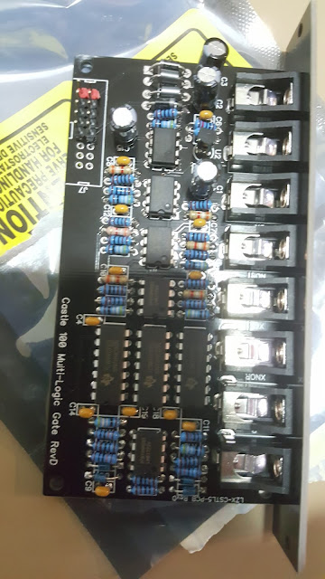
LZX Castle - Video synth - 100 MultiGate

This is the 5th module for the LZX Castle synth.
Its all DIY. A great way to learn electronics.

The module is in Eurorack format

The Multi-Logic Gate has 2 inputs and 6 outputs (XNOR, XOR, NOR, OR, NAND, and AND).

Look up a truth table for those functions.
For more on logic circuits read this:
http://djjondent.blogspot.com/2017/08/cmos-useful-chips-for-lunetta-synths.html
and TTL (Transistor Transistor Logic)

Basically it's a way to combine two stigmatized (inputs) in interesting ways via binary logic.


SN74HC00 devices contain four independent, 2-input NAND gates.
They perform the Boolean function
Y = A × B or Y = A + B in positive logic.


LZX - Castle
Introduction
00_000 ADC - Analog to digital converter
01_001 DAC - Digital to Analog converter
02_010 Clock VCO
03_011 Shift Register
04_100 Multi Gate
05_101 Quad Gate
06_110 Counter
07_111 Flip flops

Links
+ LZX industries
+ CMOS
----------------------------------------------------------------------
Video Index page

Sunday 11 November 2018

LZX Castle video Synth - 101 quad gate

Some build pics of the LZX quad gate module.
This is in Eurorack format.
The LZX official site describes it thus:
"The Quad Gate uses a single quad logic chip and combines them in 4 different ways."
(A single CMOS input/output is called a Logic Gate.)

The Quad gate is similar to the multi gate in that it uses logic gates for binary combination, but it uses a single gate type (ex. Xor. Depends on what you build it with. I (Philip) suggest xor). There are 2 sets of 2 inputs. A1, b1 and a2, b2. These have they're own outputs, out1, out2. But there are 2 other outputs that are some combination of inputs and outputs to make further interesting combinations.

The important component is a CMOS logic gate.
I'm using a CD4070BE in this build but alternatives are the CD4011 and CD 4001


The CD4070 is a quad XOR gate.
It has four Exclusive OR gates. It has two inputs per gate.
A true output results if one, and only one, of the inputs to the gate is true. If both inputs are false (0/LOW) or both are true (1/HIGH), a false output results.
A way to remember XOR is "one or the other but not both". 

------------------------------------------------------------------------------------------------
 Alternatives:
The 4001 - NOR gate (NOT - OR)
It's an inverting OR gate.

 A true output (1/HIGH) results if both inputs are false (0/LOW).
 If either or both inputs are true (1/HIGH), a false output results.
(this is the reverse of the NAND gate)
Notice the small circle at the output on the schematic symbol. This means that the gate is inverting. 
Remember that a NOT gate is an inverter. 
 ------------------------------------------------------------------------------------
Alternative:
The CD 4011 - NAND gate (NOT - AND)
It's an inverting AND gate.
This produces a false output (0/LOW) only if all its inputs are true (1/HIGH)
If either or both inputs are true (1/HIGH), a true (1/HIGH) output results.
(This is the reverse of the NOR gate)
---------------------------------------------------------------------------------------------
So it may be interesting to build these 2 alternatives.
Back to the build.


+Patch 1


A post shared by jono (@dj_jondent) on

For more on the patch click here
http://djjondent.blogspot.com/2018/12/lzx-cortex-castle-quad-gate-patches.html


LZX - Castle
Introduction
00_000 ADC - Analog to digital converter
01_001 DAC - Digital to Analog converter
02_010 Clock VCO
03_011 Shift Register
04_100 Multi Gate
05_101 Quad Gate
06_110 Counter
07_111 Flip flops

Links
+ LZX industries
+ CMOS
----------------------------------------------------------------------
Video Index page