Monday 23 May 2022

Elk Elektroniks Workshop Meeting, Sat, 21st May 2022

 It's been too long since the last meeting.
Covid virtually shut everything down last year but Australia is tentatively returning to normality.

They call this the "New Normal".

Anyway, facemasks and check-ins seem to be a thing of the past ... let's hope so.


This is the first Elk Elekroniks meeting in a long while. I understand the plan is to hold one every 2 months.

So the next will be in July, 2022.


80T


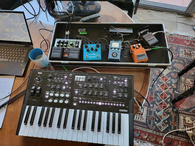
Korg Wavestate.


80T 


Many thanks to Heather for her demo of the Koma Elektronik Field Kit


Cool way to experiment with electronics
Thanks to Ed of Elk Elektroniks for holding these meetings.

Triton - New Album

 Many thanks to Ed for kindly recording this live  on Sat 21st
at his workshop.


Wednesday 18 May 2022

SMD Soldering Tutorial | Guide | Tools | Tecniques | Stencil

...

 Some  of the components used in the video

TS100 Mini Portable Electric Digital Smart Soldering Iron Programmable 65W
Looks very useful. Small and portable.
 

compatible with DC12-24V laptop power, car power and Micro USB interface mobile power.
Reprogrammable: Connecting to the computer, you can set your own temperature rising curves and custom
EU certification
 
These TS tips are designed for the TS100 soldering iron
-------------------------------------------------------------------------

These 900M tips are for Hakko,  models


 ....


Tuesday 17 May 2022

Next Elk Elektronics Meeting - 21st May

 The next Electronic Music meeting is this sat.. 21st May.

Big Room - NLC - Build notes Part 3

 These are my build notes for the  NLC (non linear circuit) Big room.
Its part 3.
 
Part 1 & 2 are here:
 
 The RCA jacks finally arrived.

These were found on Ebay.

https://www.ebay.com.au/itm/303336481628


Almost there.

Andrew recommends as short a length of RCA cable as possible is best.
Suggested tanks:

https://www.tubesandmore.com/products/reverb-tank-mod-4fb3a1b
or

https://www.amplifiedparts.com/products/reverb-tank-mod-4fb3a1b
 
Specs:
Long (16 ¾") 2 Spring Unit , Long Decay (2.75 4.0 seconds)
Input Impedance 1475 Ohms, Output Impedance 2250 Ohms

Input Grounded/Output Grounded
 

Korg wavestate - Making new set lists and populating them

Set Lists allow you to access quickly up to 64 presets" or performances.
There are 4 banks of 16 buttons.


Part A
The easiest way to add a new set list  slot is with the wavestate editor.


right click and open the set list editor


You will see a page like this:


--------------------------------------------------------------------------------
Part B

Now you need to load that new slot into the wavestate's memory.

Press Utility

You will see on the display the "System Setup"
The first line is the set list.
Use the encoder to scroll through your list of "set Lists"
Hit enter to load into memory.
---------------------------------------------------------------------------------------------------

Part C

Now you need to populate the new slots.

Start with Bank A, slot 1.

1. Select the Performance that you'd like to assign.
2. Press the SET LIST button, so that it is lit.
3. Hold WRITE and press the Slot to which you'd like to save
    (A1 in this example).

 You will see the Write page appearing on the display.
 Slot A1 is already selected. 
To change the Slot, press another button.

4. Press WRITE, 
 The display will warn you that you are about to overwrite the slot.

5. Press ENTER to confirm.

t


Thursday 12 May 2022

Comdyna GP-6 - introduction to the patch bay

The Comdyna GP-6 is an old analog computer from 1968.
It's great for solving differential equations.
This particular machine is being repaired. When it's running I'll do some demos
hopefully with some synths.

I've ordered a THAT computer which I'll compare with this.

This post is mainly a exploration of analog computer components 
but using the GP-6 as an example.
They all look pretty intimidating at first.
but the components belonging to most analog computers are fairly common...
Potentiometers, comparators, integrators, inverters, summers, multipliers, etc.
Many of these circuits use op-amps.


According to the Comdyna site, "Each GP-6 is a self-contained unit capable of simulating linear and non-linear systems of up to four state variables. Over 2000 GP-6 analog computers have been installed in over 400 university, government and commercial research laboratories."
 

Of course there is no keyboard or memory.
All programming is done with banana patch cables.
 
Virtually all analog computers have 3 basic elements:
1. Potentiometers (coefficient potentiometer).
2. Inverter / Summers
3. Integrators
 
 
-----------------------------------------------------------------------------------------
 
Below are  the COEFFICIENT POTENTIOMETERS . . . 
There are 8 of them.
Its the best place to start .... its how you input data.
These are ten turn pots, which  are used to input values (or coefficients) of the problem to calculate.  
The 8 coefficient potentiometer knobs dial in analog voltages.
 
Settings are displayed by the digital voltmeter in the POT SET mode.....

The coefficient potentiometer (pot) is a variable resistor (in effect a voltage divider )
It outputs a voltage which is some fraction of the input voltage. 
The output (the wiper arm) is usually connected to the input of one of the computing components  
 

The left two pots: Y/POT ADDRESS & X ADDRESS
These two rotary switches enable amplifier outputs and potentiometer wipers to be selected for digital voltmeter readout or output to an X-Y monitor such as an X-Y oscilloscope or X-Y plotter.
 
The MODE SELECTOR switch is positioned to POT SET for potentiometer setting and other check-out operations. Otherwise the switch is set to OPR.
 
POWER & COMPUTE TIME
(extreme right pot)
In addition to power on/off the COMPUTE TIME switch serves also to adjust the compute time or integrate period in a range of 10 to 100 scaled seconds. The time base ramp may be selected the X ADDRESS switch, TIME position, to be the XY plotter or oscilloscope horizontal axis.
 

On the patch panel the Pots connect to these central yellow bananas. Numbered 1-8


Notice that 6 of these are connected to ground. (1-6)
These only have two connections.

Notice that Pots 7 & 8 have 3 connections.
The lower jack is free floating.
So you can connect a different voltage (other than ground)
to the lower jack.
So the output can even be a -ve voltage
 
--------------------------------------------------------------
In total there are 8 op-amps.
 
These make up the Inverters / Summers & Integrators
 

Integrators 


There are 4 integrating amplifiers on the top of the patch bay.
They are numbered 1,2.3.4. 
Integration is probably the most important operation available on the analog computer.
 
What is an integrator?
It's an element whose output signal is the time integral of its input signal. 
In other words tt accumulates the input quantity over a defined time to produce a representative output. 

The op amp produces the integral conversion of the initial input voltage.
Integration is time dependent.
The important bit to remember is that the negative feedback loop uses a capacitor. 

Intergators can be found in the modular synth world.
I understand that the Make Noise Maths and the Serge slope generators uses integrators
as well as in some state variable, LP & BP  filters eg Polivoks and WASP .

Summers

There are also 2 summing amplifiers in the centre of the patch bay
These are numbered 5 & 6.
These can't do integration
 
 
Summing amplifiers are also known a voltage adders.
These circuits use op-amps to add.
Summers can be either inverting or non-inverting.

In any non-inverting summing amplifier, the output voltage is in phase with the input voltage.
This is a great circuit for adding two or more voltages without amplification.

Inverters

There are also 2 inverting only amplifiers at the very bottom.
They are numbered 7 & 8.
 
You can also see two multipliers above the inverting amps. They aren't numbered.

Here the output signal will be 180 degrees out of phase to input signal.


Notice the non-inverting (+ve) input is grounded and the feedback resistor connects to the inverting input.
Vout  = Vin* (R2)/R1


Expert sleepers ES-9 & Abelton Live CV Tools - basic setup

I just got this module from Expert Sleepers.
This is a basic set up guide for myself.
As I learn more about it, I'll update.
Do let me know if there are any mistakes.

In order to use Abelton's CV tools, you will need Abelton 10 or 11 and a DC coupled Audio interface.
CV tools is a Max for Live pack. You can download this from the Abelton website.
Its made up of 10 Max for Life devices
It sends DC signals through via your audio interface.


You also need floating ring cables (unless you are using a ES-9).
These have a 1/4 inch plug (6.3mm) on one side and a 3.5mm plug on the other side.
The side connected to the audio interface is the 6.3mm TRS jack, the ring is not connected, it's "floating".

BTW, abelton isn't  the only CV generating software:
Other's include 
As far as DC coupled audio interfaces:
I have a MOTU 828 mk3. Works great at sending CV out to the modular.
The  UA (Universal Audio ) Apollo 8 also works well.
Most interfaces are good at sending CV out to the modular but not great at receiving them from a modular
as they have filters that try to remove CVs as they enter the interface (for protection).

In this post, Im using the expert sleepers ES-9


The Main instrument of CV tools is a Max for Live device called "CV Instrument".
You will find it under "Places/packs" in your abelton menu


When installing the ES-9 as an audio interface  in Windows, you need to download a driver.
(not needed for Macs or Linux).


These are the abelton settings.

Audio tab under preferences


Inputs -- all 1 - 16


outputs 1-8 on the ES9 module correspond to 9-16 in Abelton
Outputs 1/2 are for the headphones. Be careful you dont send CV to these outputs or you will destroy your headphones.


Do some VCO calibrations

Press the calibrate button


Plug the output of your VCO into input 1.
You will see the input light up.
Set up the input on the right of the screen

I'm using an Erica Synths Pico system III.


and the abelton level for the CV instrument will also indicate a audio signal.


connect the ES-9's output 1 to V/oct input of your VCO
(This corresponds to output 9 in abelton)

This is the left green cable.

Remember, on the ES-9 module, all the black sockets are outputs.
The white ones are inputs.

So you have the possibility of 14 inputs on this module.


Tune to C3


You might have to do this a few times.
If the VCO pitch range/scale is to low, CV tools may not be able to calibrate.
Just repeat

Should go something like this:


Once you have done this pop a midi clip into the CV instrument 
and press play.

You should hear the notes being played.


There are quite a few other CV tools to use under abelton, such as:

CV Triggers

Rotating Rhythm Generator


CV envelope followers


CV in


Clock in'
clock out
CV Utility