Showing posts with label sequencers. Show all posts

Wednesday, 10 September 2025

TSNM buchla format - build notes - part 2


 This PCB dates from 2017 ..It's a  Mark 1
There are modern ones using Teensy 4.0 ..... Mk II
which you can still buy.

This is part two on my build notes.
Part 1 is here:


Links

This  Mk I uses the old Teensy 3.2.
....


C22, C23 and IC 6 are not needed if your PSU has +5V


C16 & C21 - are these part of the +5v section of the PCB?
I've soldered c16 in anyway.


C6 --- DNP ??? do not place?


1N5819HW 2 D1, D2 DO-41 schottky rectifiers 511-1N5819


L1 = ??
L2 = ferric bead.
These are connected in parallel ... across either side of the PCB.
Thus I used one ferric beath .. the through hole one. (L1)


Caps : 47uF x 2 


-------------


C17 - 100n (SMD ceramic)?? I think this is not right.
looks like an electro maybe 33uF ??
Is it C21 in the BOM??
-----------------------------------


MPR121 board & headers
It's a Adafruit 12-Key Capacitive Touch Sensor Breakout. This connects to the touch plates of the front panel

Cut the trace on the bottom of Teensy next to VIN pin to separate VIN from VUSB. This prevents 
powering the Teensy simultaneously from USB and the eurorack power supply. 


Teensy 3.2 


The two pots - 10K B ... linear (B103)
Encoder


position  the two displays and LEDs


The lower header is tricky.
I had to do some gentle bending of the ends.

you need to keep enough room for the two matrix displays... the legs aren't long


Bend these headers so you can solder them directly to the front panel


This is a side on view

 to be continued.....

Thursday, 27 March 2025

My 5U sequencer setup

 Currently I have five sequencers in my large format 5U setup

1. Moog 960
2. Two q960 synthesizer dot com  sequencers
3. Klee
4. MFOS sequencer.

The MFOS is difficult to clock without a mod.
These modifications often involve using a simple op-amp circuit (like a TL072) and a CD40106 inverter to boost and shape the incoming clock signal.
In some cases two CD40106 hex inverters connected in series may be necessary in order to give the gates and triggers being fed to the MFOS gear CMOS characteristics.
The op-amp acts as a buffer and gain stage to amplify the incoming clock signal. The CD40106 then inverts the signal and shapes it into a clean square wave that the sequencer can understand.


Till I get around to doing this I've found that the output of the MFOS sequencer drives the others quite well. Here is the basic patch.


Saturday, 24 February 2024

Wednesday, 22 February 2023

STOCHASTIC sequencers

 I've been coming  across a few STOCHASTIC sequencers recently.

The other day a friend showed up with a Oxi One

This has many more modes other than Stochastic, but I found that mode really interesting.

So what are Stochastic patterns?

These are patterns that are generated randomly, allowing for endless generative ideas in music production. These patterns can be used to create unique melodies, rhythms and structures in music.
There are quite a few systems and sequencers, eurorack modules that embrace this idea, and the list is growing.
I think we should embrace these new tools.
so musicians can explore new soundscapes and create unique compositions that would otherwise be impossible to achieve.


This is a eurorack module from Stochastic Instruments.

Below is the O-Blek
Its a MaxforLive stochastic sequencer with individual length options to offset and produce dynamic ever- changing patterns easily in Ableton Live.


Another Eurorack module which uses Stochastic ideas is Vermona's Melodicer

The two primary modes are dice and real-time.
- dice mode creates a melody and holds it until a new rhythm or melody is seeded into memory.
- real-time mode continuously generates random patterns based on the current settings.

The 12 sliders each have an associated note, and turning up that slider will increase the 
probability that the corresponding note will be played. 
Note value sets the clock division from whole to 32nd notes.

This sequencer uses cycling '74


Radioaktivnost is a 16 step sequencer for software and hardware which is clocked by radioactive decay.
How cool !!

These are just a few examples Ive found using a quick google search.
Im sure there are many more.

So in summary the Stochastic sequencer isn't your standard sequencer.
It doesn’t repeat itself and you don’t program fixed steps for variation.
Instead you duet with it by starting with the fundamental musical settings such as  pitch, 
duration, octave and various transition events. 
By changing the basic probability of these settings the melody will evolve.

I think Stochastic patterns allow for a level of creativity that is unprecedented in music production. 

By leveraging the power of randomness, musicians can explore a variety of musical ideas and find inspiration for their own compositions. With this approach, musicians can also create compositions with an ever-evolving structure - making sure that no two performances are ever the same!

Tuesday, 13 September 2022

Synton Fenix III - sequencer companion notes - 2

 This is part 2 of my companion notes for the fenix III sequencer.
 
 
Part 1 is here:

Note that the patch points are colour coded.
+ Inputs = Black
+ CV out = blue
+ Bus in/out = yellow
+ CV step input = grey
 
+ It is NOT OK to interconnect the blue outputs
+ It is OK to interconnect black inputs
+ It is OK to interconnect any number of yellow outputs
       These yellow outputs are binary (gates ... >7V or <1V)
       If one or more of the interconnected yellow sockets is HIGH, then all will be HIGH.
------------------------------------------------------------------------
Buffer Modules.
This module operates only for Logic signals ... eg those from the Yellow Bus outputs .
A Buffer is a special Logic gate. It's a non-inverting amplifier.
 
It is recommended to use a buffer module when connecting the yellow Bus to a normal gate source or an input (such as the clock input) which has internal patching.

A buffer will turn a non-buffered output (yellow jacks) into a buffered output.
When in doubt it doesn't hurt to use a buffer. Its a safety module.


--------------------------------------------------------

----------------------------
 
The Master clock module controls the speed of the sequencer
 
The Clock frequency can be set by the frequency knob
and modulated with an external voltage at the FM1 and
FM2 input or by external Midi
 
There are 5 clock outputs:
Clk out, 
Out x 4
Out/4
Out/16
Out/32
 
 
The Clock outputs are I understand to be same voltage range as Gates .. that is ... 0 to +8V
 (need to confirm with a multimeter) 

If you want to connect the Fénix with an instrument based on S-Trigger (Vintage Moog 
or Korg MS 20 etc), you need an S-Trigger converter. 
If you want to use an S-trigger to control the Fénix, you can connect the S-trigger to
 the (-) input of the comparator and the output of comparator
can be used as gate. You'll have to look for a correct setting with the control knob.

The CV out is the CV of the Frequency knob. 
You can use this as an additional control voltage. 

The R/S and Reset inputs need Gates to work.
Anything larger than +5V is high
Anything under +1V is low
 ------------------------------------------------------
 
The 3 main sequencers (C1/B1/A1) have some unique input controls:
 
To clock the sequencers using an external sequencer you'll need
a +5 gate (or larger).
A signal larger than 5 volts is considered
high, and a signal that lower than one volt, low. 
The gate and trigger outputs produce such a signal.


Triplet & Duplet


To be continued...

Sunday, 4 September 2022

Synton Fenix III - sequencer companion notes - 1

 Some personal notes to help with the official manual

The Fenix III is a wonderful sequencer. 
One of the most flexible Ive every had the good pleasure to own.
It is totally modular.
 
You can view it as three main CV/Gate sequencers
with a 4th expander sequencer
The sequencers are a bit confusing at first.
I'll divide them into CV & Gate parts, then see how they work together.
 

The CV sequencers

From top the CV sequencers are labeled: C1, B1, A1 (blue knobs)
The 4th (expander) sequencer, named A2, has red knobs.
The sequencers produce CV voltages between 0 & 8 volt.
These are the CV outputs of the sequencers:


They can be clocked via the master clock, external MIDI or external CV.
By default, the master clock is connected to all 4, but can be overridden 
with a signal at the clock input or CV-step input

Sequencers B1, C1 and A1 are pretty standard 16 step.
Forward, ping-pong, random modes.
A2 is an expander of A1
The A1 expander can be 16 steps, 2 x 8 steps, or in Inverse Mute mode.
 

The Gate sequencers


There are 4 of these: C4, B3, A4 & A3
It is important to understand the difference between gate and clock signals
A gate is a continuous high signal.
A clock has a high & low state for every step.
The clock can be standard (50% high / 50% low) or variable (called a PW clock) .
The PW (pulse width) clock can be changed ... eg (10% high/90%low or 30% high / 70% low , etc  etc).
We can even apply a CV to modulate this pulse width.
 --------------------------------------
C4-C1
The C4 Gate sequencer is linked to the C1 CV sequencer
 

 The C4 gate sequencer uses 3 position toggle switches (as do all the other gate sequencers).
In the manual, C4 is called Gate expander 1 (page 17).
The extreme left toggle with the yellow cap switches between Gate/clk/PWM.clock.
 
The PWM clock is always the master clock and not any external clock.
Thus the Clk setting can be any external CV used to clock this sequencer
(such as an LFO)
or the master clock if that is what is timing this sequencer.

The 16 toggles (above the rotary encoders) select between Yellow switch/off/clock patterns.
Up = Yellow switch pattern; Middle = off; bottom = clock pattern.

This means that if the switch is in the bottom position, the output will have a clock signal,
and if it is in the top position, it will have whatever the yellow toggle is displaying.
...........................................................................
 B3-B1
The B3 Gate sequencer is linked to the B1 CV sequencer.
 
Slight difference to c4-c1.
In the manual, it's called Gate expander 2 (page 18). 
This gate expander has 2 outputs (row 1 & 2) and runs in sync with the CV sequencer B1 .
 
The extreme left toggle with the yellow cap switches between Clock/skip/PWM.clock.
The extreme right toggle switches between rows 1 & rows 2
The 16 toggles (above the rotary encoders) select between Row 1/ off / row 2.
 Up = row 1 pattern; Middle = off; bottom = row 2 pattern.
 
 
 -----------------------------------------------------------------------
The A3 & A4 gate sequencers
 

The A3 gate sequencer has two rows of outputs -- row 1 (top), row 2 (bottom).
You select which row using each of the 16 switches above the pots.

The A3 gate sequencer exits from Gate output A.
Its outputs are PW/ Row 1/ Row 2
It is identical in function to the B3 gate sequencer

The A4 sequencer outputs via "Gate C4".
(I wonder if this was a mistake in the panel design ???
was it supposed to be A4??)
Its outputs are PW/Mute/Out/Trigger
It functions much like Gate sequencer C4


I'll add to this page over time.
please let me know if there are any mistakes.

Saturday, 26 February 2022

herbs and stone - liquid foam

 Some build pics of the Herbs & Stone module.
This is from a company in Italy called Liquid foam.
 

It's a monophonic analog "groove box" that revolves around a dual sequencer designed to encourage complex pattern exploration

This version uses uses bananas, though there is a 3.5mm jack version.
The panel size is neither 3u or 4u. so it wont fit into a euro case (unless you have the eurorack version) or a serge case

Gianluca, the  designer,  posted a PCB and faceplate to me.
I'll need to find the parts myself., build it, then make a case.

Looks like a straightforward build. I think this is suitable for a beginner. 
There are no SMD components. The parts easy to find & are well spaced. etc
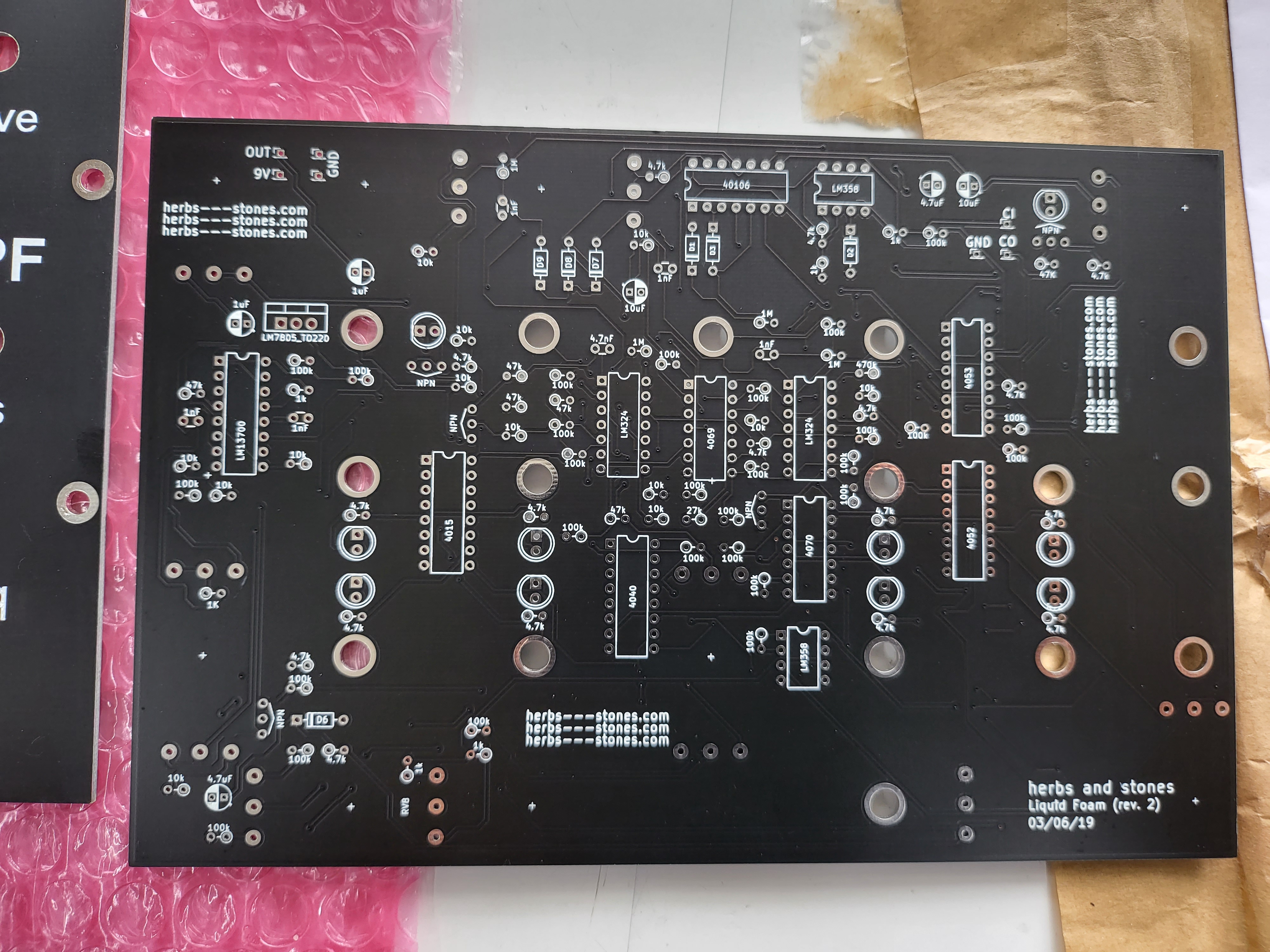
 
Lots of CMOS ICs which I mostly already had in my little store of parts.
What I didn't have was purchased from Tayda & Mouser


Links
Here’s a pdf of the manual.
+ Herbs and stone Liquid foam - instructions (personal)

All component values are screen printed on the PCB apart from diodes (1n4148) and NPN transistors (2n3904) which have only a symbol to indicate the component rotation.


The liquid foam uses a 9V power supply. I understand that this version uses a LM7805 regulator. (I found that I was able to power it with an old 6V DC adapter).
The build notes say you can use a LM7809 regulator if you are using a +12V  power supply


Get the IC sockets on first.
These are the ICs needed.
cmos:
40106  ... logic Ic ... Hex Schmitt - trigger inverter
4069UB .... hex invertering buffer   ,,,unbalanced
4070    .... XOR gate
4040
......  divider/ripple counter/Binary counter.
4052
..............Dual 4 channel multiplexer
4053 1x - on order
4015 .....
8 position shift register.
\----------------------------------

op amps:
lm13700 1x yes
lm358 2x yes
lm324 2x yes
----------------------------------------

diodes (1n4148) and NPN transistors (2n3904) ..
solder these on next .

----------------------------
Resistors next


-------------------------------

Capacitors.... longer lead into square hole.
The white half is -ve


Voltage regulator:
LM 7805

lm7805 (TO-220) or lm7809 (if you use a 12VDC PSU)

Surface components are mounted.
next push in the ICS... into their sockets
TThe Pots go on the other side of the PCB, as do the LEDs.

Its wonderful when everything just works the first time.

+ Herbs and stone Liquid foam - instructions (personal)

Saturday, 30 October 2021

Mother 32 - sequencer - editing a pattern - step mode

 To edit a sequence use Step Mode

1. Press SHIFT & STEP

2. Press The RUN/STOP button to hear the sequence.

3.  as the sequencer can only display 8 steps at a time we need to use
     the top four (1-8, 9-16, etc) buttons to jump to different bars.
 
4. We can turn ON or OFF a step by pressing the key associated with that step.
     Do this while the sequencer is running.

5. To further edit each step press SHIFT and the step you want to edit.
    The step being edited will start flashing. 

 5a   You can  now add RESTs & ACCENTs using the associated
        two buttons on the left
 5b  You can also change octaves during this stage (use the arrow keys).
 5c . Changing the step length is also done here. 
        Use the tempo knob to change the length from 1 to 8
        The LEDs will indicate the length.

6. To exit hold SHIFT + the step


------------------
Also check out the 8 LEDs. These will light up when you are playing a sequence.
LED 6 indicates a ratchet. 
LED 5 indicates a glide 
LED 8 indicates a hold /rest
LED 7 indicates  an accent
-----------------------------------------------------------

Remember to SAVE your CHANGES.


1.Press SHIFT + Record (1 second ... the LED indicating the memory slots blinks yellow)

2. Press SHIFT + Record again

Wednesday, 11 August 2021

building of the Klee sequencer - part 2

This is part 2 of my building of the Klee sequencer
The Klee is a classic sequencer.
Sometimes referred to as a "shift register sequencer", the inspiration is from 2 sources I understand:
Don Buchla's 266 SOU and Ken Stone's Gated Comparator. 
The Klee circuitry was designed by Scott Stites and uses two CD4034s as its shift register.
It's design has been adapted to Eurorack , 5U MOTM, 4U Serge & Buchla  formats.
 
Other modules such as the turing machine & the noise ring also use a shift register.
These are worth exploring.

Part 1 and 3 are here

It's not a difficult build. Just a long one.


-------------------------------------------------------------------------------
The lower mother board is made up of a digital and an analog side.

Digital side now
 
 
R71-R78 --- do not install anything in these positions (leave them empty)
These are marked with a *


100K resistors first
There are 24 of these. 
They are 1%, 1/4W
R 23 TO R26, R30, R49, R52 TO R62, R81 TO R84, R89, R90, R94


 Metal Film Resistor 4.7Kohm 1%
R31, R48, R85 TO R88 
and R32 TO R47   these are the sixteen 12V LEDs ?


So what's the difference between a Klee and a standard sequencer?
As mentioned earlier ... this uses bit shift registers.
A standard sequencer can only have one step active at a time, but a Klee can have many active steps.
If more than one bit is active , the slider values will be summed.


R91 - bom says 270K
Was supplied a 270ohm 
I'll use a 270K resistor in the build.


Film Capacitors 100volts 1000pF
Six of these - C6 TO C10, C18


The 22K resistors ... there are 25 of these according to the BOM however they aren't numbered.
Through a process of elimination, the resistors are
R1 to R22, 50, 51,80. These are all 5% tolerance, 1/4 W


---------------------------------------------------------------
Back to the Analogue Board
It is the source of the signals required for the Variable Range control options. It is also the board that directly interfaces to the power supply, and the board that involves all of the calibration of the Klee. 
 
Dont install this trimmer (R41) on the analog section of the mother board.
If any of the variable range options are installed, then you should refrain from installing R41. The front panel Variable Range Control will take over the function performed by that trim pot
 
 
I accidently installed the trimmer, and had to remove it later

 
-------------


It's time to install the ICs
The OP amps of the Analog board first
  .. 072 & 074s


Note W2.
This is a jumper. 
W2, is only installed if any of the variable range options are not installed. 
 
(Note that if you are using the older build manual they will mention jumper W1, which I can't see on this Euro board... W1 should only be installed if the power supply, for some reason, has only one ground connection.... as is the case with Eurorack. In other words, if you have a power supply with only one ground lead, install W1. This ties the analog and digital grounds together at this one point).


J16
J16 provides the signal(s) to the front panel Variable Range control(s).
In the old build manual, you needed to put a jumper here I understand.
The manual for the Euro-Klee  says
"You do not need to install any of these jumpers – it’s all taken care of on the daughterboard."


The CMOS ICs - CD4051, & 4066 x 4

------------------------------------------
The digital board

CD4071 - U3, Quad 2 Input OR Gate
CD4013 - u5 , Dual D Flip Flop
CD4053 - Quad 1 of 2 Switch -  multiplexer - u9


CD4093 Quad Schmitt Nand Gate x 3
 U4, U12 – U13


LM358 Dual OpAmp x 2.... U1, U8
 
 LM324 324 LOW POWER QUAD OP-AMP IC x2
U14, U15
 
CD40106BE Hex Schmitt Trigger x 3. U2, U10 – U11
 
Transistors 
Only one type of transistor is used throughout the Klee Sequencer – the 2N3904 NPN transistor, and they’re all located on the Digital Board. These transistors are used to drive the clock, reference and gate bus LEDs. There are six of these transistors.

CD4034 x 2.... U6 & U7
they're 8-Stage tri-state bidirectional parallel/serial input/output bus registers
 
 The board is pretty much done.
Now time for the headers
 

----------------
 
Putting the headers in is a fiddly process.
Here is a list of the headers:
Analogue Board: SIL Pin Rows --- J1, J3, J5, J6, J7, J8, J10, J12, J13, J15, J16 
                            MTA Headers --- J2, J4, J9, J11 (not placed in 2015+) 
Digital Board: SIL Pin Rows --- J2, J4, J5, J8, J9, J11, J12, J13 
                             MTA Headers --- J1, J3, J6, J7, J10 (not placed in 2015+) 


I like to line up 4 at a time and solder, then pull the boards apart and reposition 4 more.


Eventually, the boards should look something like this

------------------

This is the top of the daughter board.
It holds the switches, sliders, pots, LEDs etc.


Some of the sliders sit on top of some of the headers we just soldered.


Socket pin shaving time to decrease chance of shorts ..
TRy to cut them as close to the PCB as possible to avoid any shorting.
Ive added some electrical tape as well
 
To be continued.......


-----------------