These are my build notes for the Wagernumb.
It's a Nonlinearcircuits module in Eurorack format.
Looks to be quite versatile. Andrew's build notes describe it as 3 or 4 modules in one:
+ Frequency Tracker
+ Frequency / Clock divider - down to 1/4096
+ VCO
+ Random or Burst generator.
Basically it's a 1-16 decoder with sync and async
modes. Just feed it 4 signals and get all sorts of complex gate patterns
from it. Runs at audio rates too so can be used as a sub-octave
generator.
I also like using it to trigger my ARP 2500's envelope generator.
Like the Numberwang, it outputs lots of complex gate patterns. The gates are around the 7V level.
My ARP 2600 also happens to trigger at this level... though 10V is recommended.
To get 10V gates, use a TTSH gate booster.

Links
+The NLC build notes are here:
http://www.sdiy.org/pinky/data/wangernumb_build&BOM.pdf
+ NLC blog
I'm guessing that the name for this module comes from the fictional television series in which the two contestants call out seemingly random numbers which are occasionally told to be Numberwang.
..

It's not base-2, decimal or any other number system I can decipher.


509???

Get those ICs and trannies on first. then the rest of those passive SMDs
I don't have a CD4046... on back order. It's a PLL or phase locked loop CMOS chip.
I ordered the wrong size chip -- a TSSOP-16 . This is way too small.
Get one in the SOP-16 format


The 4046 arrived.
Mouser: 595-CD4046BNSRE4

Pots - two B100K


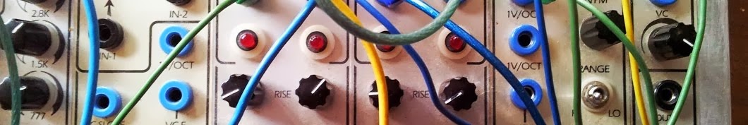
Using the module:

There are 4 inputs on the left of the module.
The group of 12 outputs produce gates.
The VCO output is for audio & CVs
As a CV Tracker / CV divider:
Use the Track input at the very top.
The phase lock loop acts as a frequency tracker. The VCO Range CV input and filter pot will determine how well it will track. You also get 12 divisions of the tracking signal, right down to divide by 4096.
Clock Divider
If you use the Divide input, you have a 12 stage clock divider, down to 1/4096. In this case,you can use the PLL tracker section as a separate and independent VCO module and get it to generate squelchy, glitchy noises or as a tracker again.
There are 12 gate outputs. This is where the divided clock exits.
1= /2
8-4 = /4
21.3 = /8
.01 = /16
41 = /32
93 = /64
12 = /128
70 = /256
26 = /512
2 = /1024
-3 = /2048
+-6 = /4096
Random CV or Burst generator.
If you use the Roulette input, it will generate semi-random selections of outputs when the input signal is high....or, depending upon how you drive it and look at the results, it is a burst generator and you can control the frequency of the bursts with the VCO CV input.
VCO
Use the VCO output at the top of the module.
Running it at audio rates turns it into a sub-octave
generator.
You won't hear anything from the VCO out until some CVs or audio is inputted into the
track or roulette inputs. The gate outputs will also fire.
You can control the frequency of the VCO with the VCO range CV input
---------------------------------------------------------------------------------------------------
Click here to return to the NLC Build Index:
http://djjondent.blogspot.com.au/2015/03/non-linear-circuits-ncl-index.html
No comments:
Post a Comment